


MCF51QE128 MCU Series Reference Manual, Rev. 3
Freescale Semiconductor 189
Get the latest version from freescale.com
Chapter 8 Interrupt Controller (CF1_INTC)
To emulate the HCS08’s 1-level IRQ nesting mechanisms, the ColdFire implementation enables interrupts
by clearing SR[I] (typically when using RTE to return to a process) and disables interrupts upon entering
every interrupt service routine by one of three methods:
1. Execution of STLDSR #0x2700 as the first instruction of an ISR.
2. Execution of MOVE.w #0x2700,SR as the first instruction of an ISR.
3. Static assertion of CPUCR[IME], which forces the processor to load SR[I] with seven
automatically upon the occurrence of an interrupt exception. Because this method removes the
need to execute multi-cycle instructions of #1 or #2, this approach improves system performance.
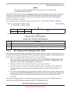
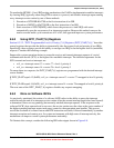
8.6.2 Using INTC_PL6P{7,6} Registers
Section 8.3.2.2, “INTC Programmable Level 6, Priority {7,6} Registers (INTC_PL6P{7,6}),” describes
control registers that provide the ability to dynamically alter the request level and priority of two IRQs.
Specifically, these registers provide the ability to reassign two IRQs to be the highest level 6 (maskable)
requests. Consider the following example.
Suppose the system operation desires to remap the receive and transmit interrupt requests of a serial
communication device (SCI1) as the highest two maskable interrupts. The default assignments for the
SCI1 transmit and receive interrupts are:
• sci1_rx = interrupt source 13 = vector 77 = level 4, priority 4
• sci1_tx = interrupt source 14 = vector 78 = level 4, priority 3
To remap these two requests, the INTC_PL6P{7,6} registers are programmed with the desired interrupt
source number:
If INTC_PL6P7 equals 13 (0x0D), sci1_rx = interrupt source 13 = vector 77 remapped as level 6, priority
7.
If INTC_PL6P6 equals 14 (0x0E), sci1_tx = interrupt source 14 = vector 78 remapped as level 6, priority 6.
The reset state of the INTC_PL6P{7,6} registers disables any request remapping.
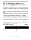
8.6.3 More on Software IACKs
As previously mentioned, the notion of a software IACK refers to the ability to query the interrupt
controller near the end of an interrupt service routine (after the current interrupt request has been cleared)
to determine if there are any pending (but currently masked) interrupt requests. If the response to the
software IACK’s byte operand read is non-zero, the service routine uses the value as the vector number of
the highest pending interrupt request and passes control to the appropriate new handler. This process
avoids the overhead of a context restore and RTE instruction execution, followed immediately by another
interrupt exception and context save. In system environments with high rates of interrupt activity, this
mechanism can improve overall system performance noticeably.
To illustrate this concept, consider the following ISR code snippet shown in Figure 8-8.