


Chapter 18 Version 1 ColdFire Debug (CF1_DEBUG)
MCF51QE128 MCU Series Reference Manual, Rev. 3
Freescale Semiconductor 369
Get the latest version from freescale.com
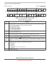
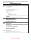
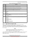
22–21
PSTBST
PST trace buffer state. Indicates the current state of the PST trace buffer recording.
00 PSTB disabled
01 PSTB enabled and waiting for the start condition
10 PSTB enabled, recording and waiting for the stop condition
11 PSTB enabled, completed recording after the stop condition was reached
20 Reserved, must be cleared.
19–16
D1HRL
Debug 1-pin hardware revision level. Indicates the hardware revision level of the 1-pin debug module implemented
in the ColdFire core. For this device, this field is 0x0.
15–8
PSTBWA
PST trace buffer write address. Indicates the current write address of the PST trace buffer. The most-significant-bit
of this field is sticky, that is, once set, it remains set until a PST/DDATA reset event occurs. As the ColdFire core
inserts PST and DDATA packets into the trace buffer, this field is incremented. The value of the write address
defines the next location in the PST trace buffer to be loaded. In other words, the contents of PSTB[PSTBWA-1]
is the last valid entry in the trace buffer.
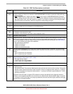
The msb of this field can be used to determine if the entire PST trace buffer has been loaded with valid data.
The PSTBWA is unaffected when a buffer stop condition has been reached, the buffer is disabled, or a system
reset occurs. This allows the contents of the PST trace buffer to be retrieved after these events to assist in debug.
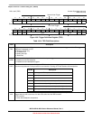
7
PSTBR
PST trace buffer reset. Generates a reset of the PST trace buffer logic, which clears PSTBWA and PSTBST. The
same resources are reset whenever a disabled trace buffer becomes enabled and upon the receipt of a BDM GO
command when operating in continuous trace mode. These reset events also clear any accumulation of PSTs.
This bit always reads as a zero.
0 Do not force a PST trace buffer reset
1 Force a PST trace buffer reset
6
APCDIV16
Automatic PC synchronization divide cycle counts by 16. This bit divides the cycle counts for automatic SYNC_PC
command insertion by 16. See the APCSC and APCENB field descriptions.
5 Reserved, must be cleared.
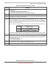
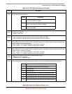
Table 18-9. CSR2 Field Descriptions (continued)
Field Description
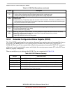
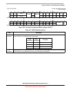
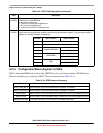
PSTBWA[7]
PSTB Valid Data Locations
(Oldest to Newest)
0 0, 1, ... PSTBWA-1
1 PSTBWA, PSTBWA+1,..., 0, 1, PSTBWA-1