


Chapter 18 Version 1 ColdFire Debug (CF1_DEBUG)
MCF51QE128 MCU Series Reference Manual, Rev. 3
Freescale Semiconductor 375
Get the latest version from freescale.com
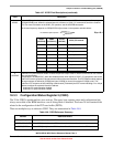
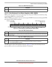
20–18
L2EA
Enable level 2 address breakpoint. Setting an L2EA bit enables the corresponding address breakpoint. Clearing all
three bits disables the breakpoint.
17
L2EPC
Enable level 2 PC breakpoint.
0 Disable PC breakpoint
1 Enable PC breakpoint
16
L2PCI
Level 2 PC breakpoint invert.
0 The PC breakpoint is defined within the region defined by PBRn and PBMR.
1 The PC breakpoint is defined outside the region defined by PBRn and PBMR.
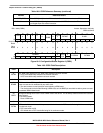
15
L2T
Level 2 trigger. Determines the logic operation for the trigger between the PC_condition and the (Address_range and
Data) condition where the inclusion of a Data_condition is optional. The ColdFire debug architecture supports the
creation of single or double-level triggers.
0 Level 2 trigger = PC_condition & (Address_range & Data_condition)
1 Level 2 trigger = PC_condition | (Address_range & Data_condition)
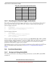
14
L1T
Level 1 trigger. Determines the logic operation for the trigger between the PC_condition and the (Address_range and
Data) condition where the inclusion of a Data_condition is optional. The ColdFire debug architecture supports the
creation of single or double-level triggers.
0 Level 1 trigger = PC_condition & (Address_range & Data_condition)
1 Level 1 trigger = PC_condition | (Address_range & Data_condition)
13
L1EBL
Enable level 1 breakpoint. Global enable for the breakpoint trigger.
0 Disables all level 1 breakpoints
1 Enables all level 1 breakpoint triggers
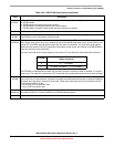
12–6
L1ED
Enable level 1 data breakpoint. Setting an L1ED bit enables the corresponding data breakpoint condition based on
the size and placement on the processor’s local data bus. Clearing all L1ED bits disables data breakpoints.
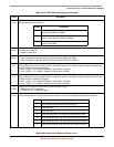
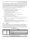
Table 18-14. TDR Field Descriptions (continued)
Field Description
TDR Bit Description
20 Address breakpoint inverted. Breakpoint is based outside the
range between ABLR and ABHR.
19 Address breakpoint range. The breakpoint is based on the
inclusive range defined by ABLR and ABHR.
18 Address breakpoint low. The breakpoint is based on the
address in the ABLR.
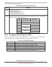
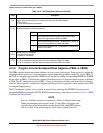
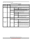
TDR Bit Description
12 Data longword. Entire processor’s local data bus.
11 Lower data word.
10 Upper data word.
9 Lower lower data byte. Low-order byte of the low-order word.
8 Lower middle data byte. High-order byte of the low-order word.
7 Upper middle data byte. Low-order byte of the high-order word.
6 Upper upper data byte. High-order byte of the high-order word.