


MCF51QE128 MCU Series Reference Manual, Rev. 3
Freescale Semiconductor 141
Get the latest version from freescale.com
Chapter 6 Parallel Input/Output Control
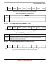
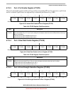
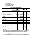
6.7.10.2 KBI1 Interrupt Pin Select Register (KBI1PE)
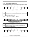
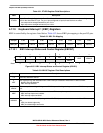
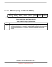
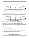
6.7.10.3 KBI1 Interrupt Edge Select Register (KBI1ES)
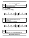
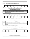
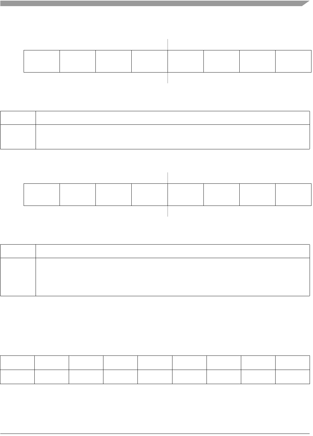
6.7.11 Keyboard Interrupt 1 (KBI2) Registers
KBI2 is controlled by the registers listed below. Table 6-56 shows KBI2 pin mapping to the port I/O pins.
76543210
R
KBIPE7 KBIPE6 KBIPE5 KBIPE4 KBIPE3 KBIPE2 KBIPE1 KBIPE0
W
Reset:00000000
Figure 6-56. KBI1 Interrupt Pin Select Register (KBI1PE)
Table 6-54. KBI1PE Register Field Descriptions
Field Description
7–0
KBIPEn
KBI1 Interrupt Pin Selects. Each of the KBIPEn bits enable the corresponding KBI1 interrupt pin.
0 Pin not enabled as interrupt.
1 Pin enabled as interrupt.
76543210
R
KBEDG7 KBEDG6 KBEDG5 KBEDG4 KBEDG3 KBEDG2 KBEDG1 KBEDG0
W
Reset:00000000
Figure 6-57. KBI1 Edge Select Register (KBI1ES)
Table 6-55. KBI1ES Register Field Descriptions
Field Description
7–0
KBEDGn
KBI1 Edge Selects. Each of the KBEDGn bits serves a dual purpose by selecting the polarity of the active
interrupt edge as well as selecting a pull-up or pull-down device if enabled.
0 A pull-up device is connected to the associated pin and detects falling edge/low level for interrupt generation.
1 A pull-down device is connected to the associated pin and detects rising edge/high level for interrupt
generation.
Table 6-56. KBI2 Pin Mapping
Port pin PTD7 PTD6 PTD5 PTD4 PTD3 PTD2 PTD1 PTD0
KBI2 pin KBI2P7 KBI2P6 KBI2P5 KBI2P4 KBI2P3 KBI2P2 KBI2P1 KBI2P0