


MCF51QE128 MCU Series Reference Manual, Rev. 3
44 Freescale Semiconductor
Get the latest version from freescale.com
Chapter 3 Modes of Operation
3.3 Overview
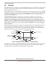
The ColdFire CPU has two primary user modes of operation, run and stop. (The CPU also supports a halt
mode that is used strictly for debug operations.) The STOP instruction is used to invoke stop and wait
modes for this family of devices.
If the WAITE control bit is set when STOP is executed, the wait mode is entered. Otherwise, if the STOPE
bit is set, the CPU enters one of the stop modes. It is illegal to execute a STOP instruction if neither STOPE
or WAITE are set. This results in reset assertion if CPUCR[IRD] is cleared or an illegal instruction
exception if CPUCR[IRD] is set.
The MCF51QE128/64/32 devices augment stop, wait, and run in a number of ways. The power
management controller (PMC) can run the device in fully-regulated mode, standby mode, and partial
power-down mode. Standby (loose regulation) or partial power-down can be programmed to occur
naturally as a result of a STOP instruction. Additionally, standby mode can be explicitly invoked via the
LPR (low-power) bit in the PMC. Use of standby is limited to bus frequencies less than 125 kHz; and
neither standby nor partial power-down are allowed when the ENBDM bit is set to enable debugging in
stop and wait modes.
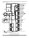
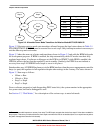
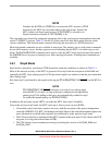
During partial power-down mode, the regulator is in standby mode and much of the digital logic on the
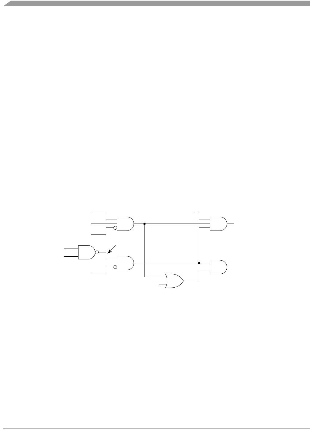
chip is switched off. These interactions can be seen schematically in Figure 3-1. This figure is for
conceptual purposes only. It does not reflect any sequence or time dependencies between the PMC and
other parts of the device, nor does it represent any actual design partitioning.
Figure 3-1. MCF51QE128/64/32 Power Modes - Conceptual Drawing
It is illegal for the software to have PPDC and LPR asserted concurrently. This restriction arises because
the sequence of events from normal to low-power modes involves use of both bits. After entering a
low-power mode, it is not possible to switch to another low-power mode.
STOP
SOPT1[STOPE]
SOPT1[WAITE]
SPMSC1[LVDE]
SPMSC1[LVDSE]
SPMSC2[PPDC]
In Stop Mode
Partial Power Down
Standby Enable
CSR2[ENBDM]
SPMSC2[LPR]
LVD Off
Standby