


Chapter 18 Version 1 ColdFire Debug (CF1_DEBUG)
MCF51QE128 MCU Series Reference Manual, Rev. 3
378 Freescale Semiconductor
Get the latest version from freescale.com
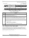
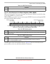
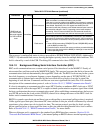
18.3.9 Address Breakpoint Registers (ABLR, ABHR)
The ABLR and ABHR define regions in the processor’s data address space that can be used as part of the
trigger. These register values are compared with the address for each transfer on the processor’s high-speed
local bus. The trigger definition register (TDR) identifies the trigger as one of three cases:
• Identical to the value in ABLR
• Inside the range bound by ABLR and ABHR inclusive
• Outside that same range
The address breakpoint registers are accessible in supervisor mode using the WDEBUG instruction and
through the BDM port using the WRITE_DREG command using values shown in Section 18.4.1.4, “BDM
Command Set Descriptions.”
NOTE
Version 1 ColdFire core devices implement a 24-bit, 16-Mbyte address map.
When programming these registers with a 32-bit address, the upper byte
should be zero-filled when referencing the flash, RAM, and RGPIO regions,
and set to 0xFF when referencing any of the slave peripheral devices.
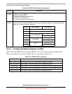
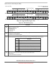
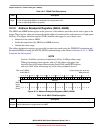
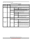
Table 18-17. PBMR Field Descriptions
Field Description
31–0
Mask
PC breakpoint mask.
0 The corresponding PBR0 bit is compared to the appropriate PC bit.
1 The corresponding PBR0 bit is ignored.
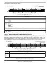
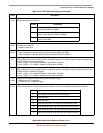
DRc: 0x0C (ABHR)
0x0D (ABLR)
Access: Supervisor write-only
BDM write-only
313029282726252423222120191817161514131211109876543210
R
WAddress
ABHR
Reset
––––––––––––––––––––––––––––––––
ABLR
Reset
00000000000000000000000000000000
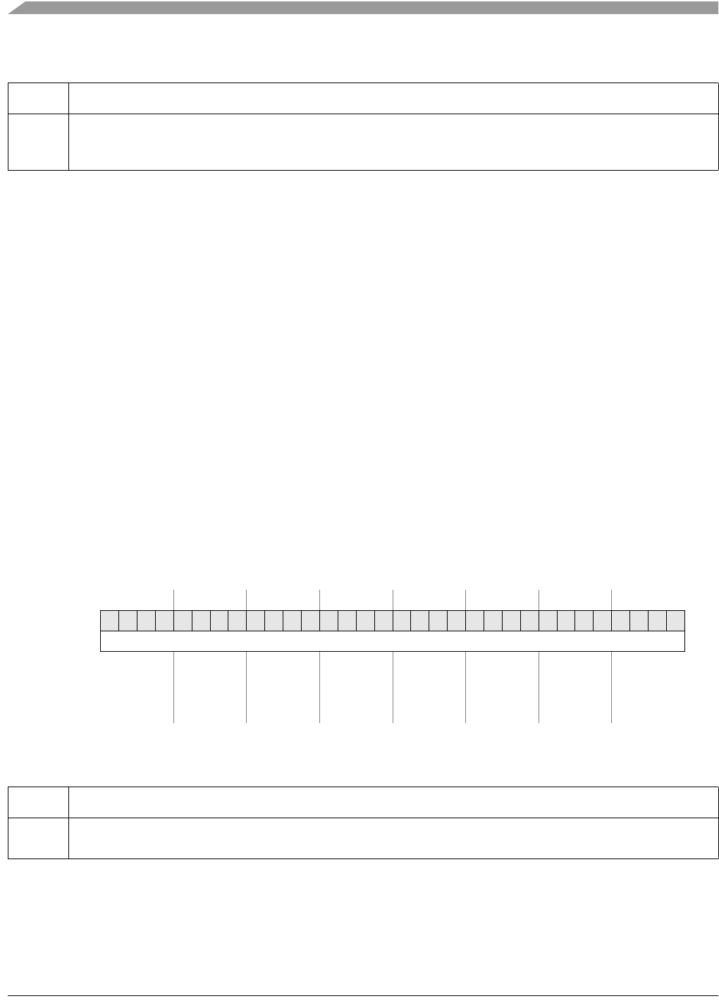
Figure 18-13. Address Breakpoint Registers (ABLR, ABHR)
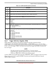
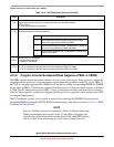
Table 18-18. ABLR Field Description
Field Description
31–0
Address
Low address. Holds the 32-bit address marking the lower bound of the address breakpoint range. Breakpoints for
specific addresses are programmed into ABLR.