


MCF51QE128 MCU Series Reference Manual, Rev. 3
Freescale Semiconductor 53
Get the latest version from freescale.com
Chapter 3 Modes of Operation
Stop4 is also entered if SPMSC1[LVDE, LVDSE] are set, enabling low voltage detect when the STOP
instruction is executed. The LVD may only be used when the on-chip regulator is in full regulation mode.
Thus, stop3 and stop2 modes are not compatible with use of the LVD.
The LVD system is capable of generating an interrupt or a reset when the supply voltage drops below the
LVD voltage.
Stop4 can be exited by asserting RESET or by an interrupt from one of the following sources: the RTC,
LVD, LVW, ADC, ACMPx, IRQ, SCI or the KBI.
3.9 On-Chip Peripheral Modules in Stop and Low-Power Modes
When the MCU enters any stop mode (wait not included), system clocks to the internal peripheral modules
are stopped. Even in the exception case (ENBDM = 1), where clocks to the background debug logic
continue to operate, clocks to the peripheral systems are halted to reduce power consumption. Refer to
Section 3.8.1, “Stop2 Mode,” and Section 3.8.2, “Stop3 Mode,” for specific information on system
behavior in stop modes.
When the MCU enters LPwait or LPrun modes, system clocks to the internal peripheral modules continue
based on the settings of the clock gating control registers (SCGC1 and SCGC2).
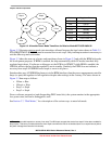
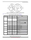
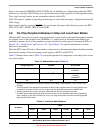
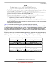
Table 3-3 defines terms used in Table 3-4 to describe operation of components on the chip in the various
low-power modes.
Table 3-3. Abbreviations used in Table 3-4
Voltage Regulator Clocked
1
1
Subject to module enables and settings of System Clock Gating Control Registers 1 and 2 (SCGC1 and
SCGC2).
Not Clocked
Full Regulation FullOn FullNoClk
FullADACK
2
2
This ADC-specific mode defines the case where the device is fully regulated and the normal peripheral clock
is stopped. In this case, the ADC can run using its internally generated asynchronous ADACK clock.
Soft Regulation SoftOn
3
3
Analog modules must be in their low-power mode when the device is operated in this state.
SoftNoClk
Disabled
SoftADACK
4
4
This ADC-specific mode defines the case where the device is in soft regulation and the normal peripheral
clock is stopped. In this case, the ADC can only be run using its low-power mode and internally generated
asynchronous ADACK clock.
Off N/A Off
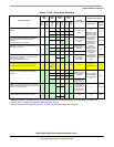
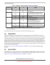
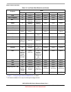
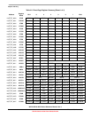
Table 3-4. Low-Power Mode Behavior
Peripheral
Mode
Stop2 Stop3 Stop4 LPwait Wait LPrun
CF1_CORE Off SoftNoClk FullNoClk SoftNoClk FullNoClk SoftOn
RAM SoftNoClk SoftNoClk FullNoClk SoftNoClk FullNoClk SoftOn