


Analog Comparator (S08ACMPVLPV1)
MCF51QE128 MCU Series Reference Manual, Rev. 3
212 Freescale Semiconductor
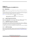
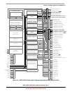
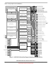
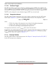
Figure 10-2. Analog Comparator Module Block Diagram
10.2 External Signal Description
The ACMP has two analog input pins: ACMP0 and ACMP1. Each of these pins can accept an input
voltage that varies across the full operating voltage range of the MCU. If the module is not enabled, each
of these pins can be used as digital inputs or outputs. Consult the specific MCU documentation to
determine what functions are shared with these analog inputs. As shown in the block diagram, the ACMP1
pin is connected to the comparator non-inverting input if ACBGS is equal to logic zero, and the ACMP0
pin is connected to the inverting input of the comparator.
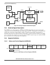
10.3 Register Definition
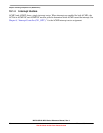
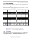
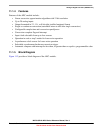
10.3.1 Status and Control Register (ACMPxSC)
7654321 0
R
ACME ACBGS ACF ACIE
ACO
ACOPE ACMOD1 ACMOD0
W
Reset:00000000
= Unimplemented
Figure 10-3. ACMP Status and Control Register (ACMPxSC)
+
–
ACMP1
ACMP0
Interrupt
Control
AC IRQ
Internal
Reference
ACBGS
Internal Bus
Status & Control
Register
ACMOD1
ACMOD2
SET ACF
ACPE
ACF
ACIE
ACOPE
ACO
ACMPx0