


MCF51QE128 MCU Series Reference Manual, Rev. 3
182 Freescale Semiconductor
Get the latest version from freescale.com
Chapter 8 Interrupt Controller (CF1_INTC)
The interrupt controller's wake-up signal is defined as:
wake-up = INTC_WCR[ENB] & (level of any asserted_int_request > INTC_WCR[MASK])
Reset state of the INTC_WCR is disabled, so this register must be written to enable the wake-up condition
before the core executes any STOP instructions.
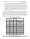
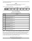
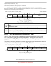
Figure 8-4. INTC_WCR Register
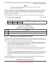
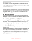
8.3.2.4 INTC Set Interrupt Force Register (INTC_SFRC)
The INTC_SFRC register provides a simple memory-mapped mechanism to set a given bit in the
INTC_FRC register to assert a specific level interrupt request. The data value written causes the
appropriate bit in the INTC_FRC register to be set. Attempted reads of this register generate an error
termination.
This register is provided so interrupt service routines can generate a forced interrupt request without the
need to perform a read-modify-write sequence on the INTC_FRC register.
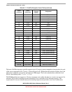
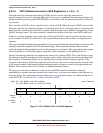
Figure 8-5. INTC_SFRC Register
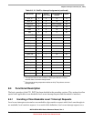
Offset: CF1_INTC_BASE + 0x1B (INTC_WCR) Access: Read/Write
76543210
R
ENB
0 0 00
MASK
W
Reset00000000
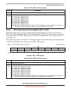
Table 8-6. INTC_WCR Field Descriptions
Field Description
7
ENB
Enable.
0 Wake-up signal disabled.
1 Enables the assertion of the combinational wake-up signal to the clock generation logic.
6–3 Reserved, must be cleared.
2–0
MASK
Interrupt mask level. Defines the interrupt mask level during wait or stop mode and is enforced by the hardware to
be within the range 0–6. If INTC_WCR[ENB] is set, after an interrupt request of a level higher than MASK is asserted,
the wake-up signal to the clock generation logic is asserted.
Offset: CF1_INTC_BASE + 0x1E (INTC_SFRC) Access: Write-only
76543210
R
W 0 0 SET
Reset00000000