


MCF51QE128 MCU Series Reference Manual, Rev. 3
218 Freescale Semiconductor
Get the latest version from freescale.com
Chapter 11 Analog-to-Digital Converter (S08ADC12V1)
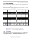
11.1.2.3 Hardware Trigger
The ADC may initiate a conversion via software or a hardware trigger. The RTC can be enabled as the
hardware trigger for the ADC module by setting ADCSC2[ADTRG]. When enabled, the ADC is triggered
each time RTCINT matches RTCMOD. The RTC interrupt does not have to be enabled to trigger the ADC.
The RTC can be configured to cause a hardware trigger in MCU run, wait, and stop3.
11.1.2.4 Temperature Sensor
The ADC module includes a temperature sensor whose output is connected to one of the ADC analog
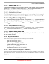
channel inputs. Equation 11-1 provides an approximate transfer function of the temperature sensor.
Eqn. 11-1
where:
—V
TEMP
is the voltage of the temperature sensor channel at the ambient temperature.
—V
TEMP25
is the voltage of the temperature sensor channel at 25°C.
— m is the hot or cold voltage versus temperature slope in V/°C.
For temperature calculations, use the V
TEMP25
and m values in the data sheet.
In application code, read the temperature sensor channel, calculate V
TEMP
, and compare it to V
TEMP25
. If
V
TEMP
is greater than V
TEMP25
the cold slope value is applied in Equation 11-1. If V
TEMP
is less than
V
TEMP25
the hot slope value is applied in Equation 11-1.
11.1.3 Interrupt Vectors
The ADC module contains a single interrupt source. See Chapter 8, “Interrupt Controller (CF1_INTC),”
for the ADC interrupt vector assignment.
Temp 25
V
TEMP
V
TEMP25
–
m
-----------------------------------------------
–=