Installing the Mail System
Connecting to the Remote Maintenance Device
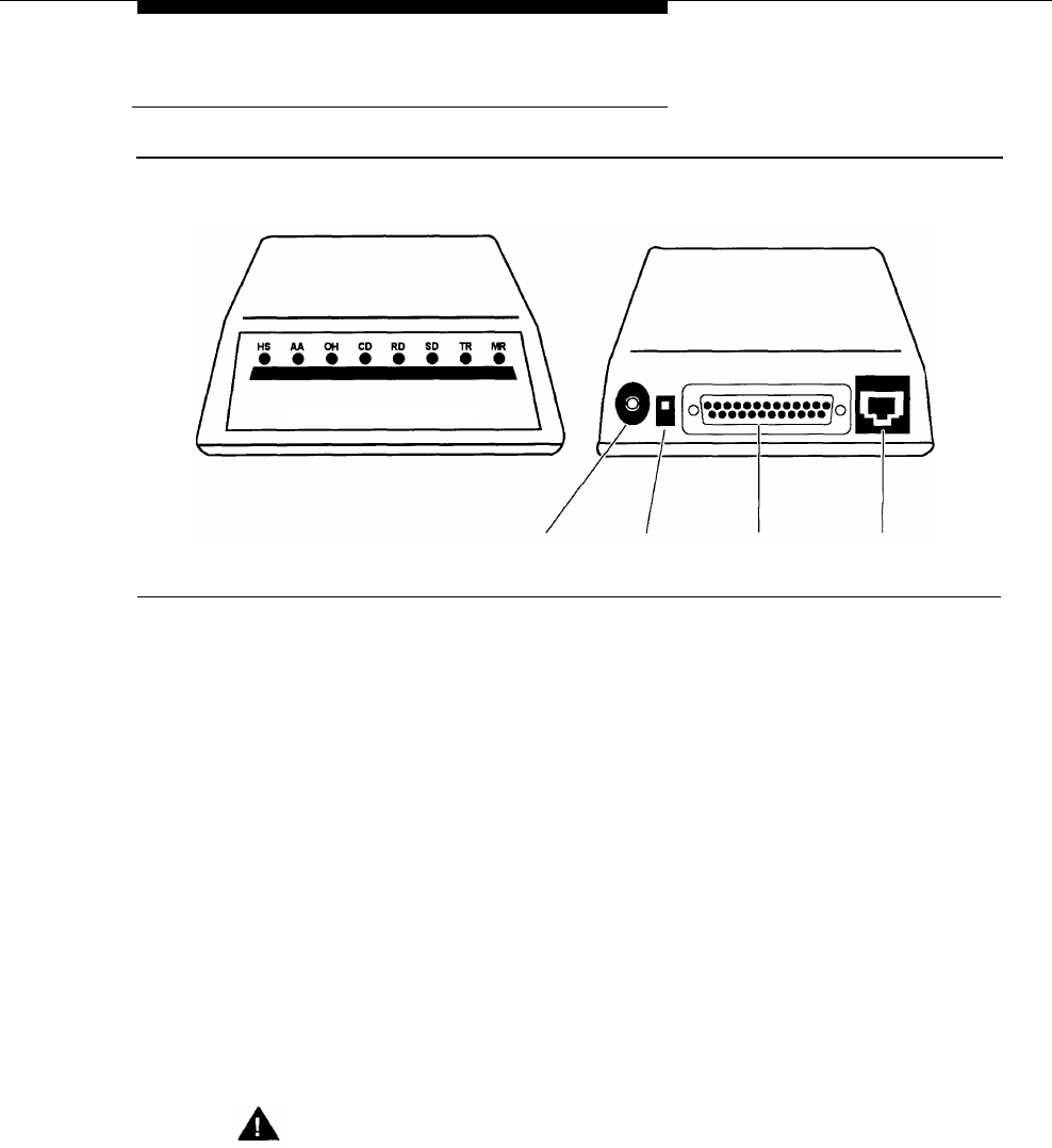
(Front View)
(Back View)
REMOTE MAINTENANCE DEVICE Mk III
DC On/Off RS–232–C Telephone
Power In
Switch
Port Line Port
Figure 2-6. Remote Maintenance Device
1.
2.
3.
4.
5.
6.
Use the modem cable provided to connect the RS-232-C port on the Remote
Maintenance Device (see Figure 2-6) to the COM1 port on the system unit
(see Figure 2-5).
Use a modular telephone cord to connect the Telephone Line Port on the
Remote Maintenance Device (see Figure 2-6) to an extension jack on the
206 module. Refer to Communications System Planning Form B1 for the
correct extension number.
Attach one end of the power cord to the DC Power In jack on the Remote
Maintenance Device (see Figure 2-6) and plug the other end into a
grounded AC electrical source.
Turn on the on/off switch (see Figure 2-6). Verify that the AA, TR, and MR
LEDs on the front of the Remote Maintenance Device are lit.
Turn off the Remote Maintenance Device.
Write the 206 module extension jack number on a label and affix the label to
the Remote Maintenance Device. Keep the extension jack number handy.
You may need it if the mail system needs servicing.
Security Alert:
Keep the Remote Maintenance Device turned off unless your mail system
needs servicing and service personnel need remote access to your
system.
Installation
2-9


