


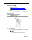
Installing the Mail System
Connecting to the Communications System
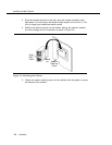
1.
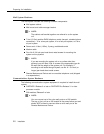
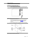
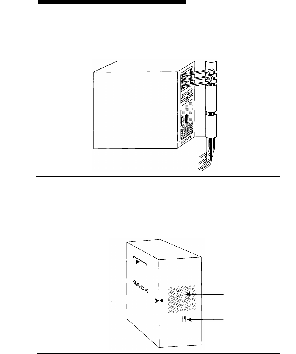
Route the telephone cords through the slots on the bracket and connect
them to the appropriate ports on the system unit as shown in Figure 2-3.
Figure 2-3. Connecting Cords to the System Unit
2.
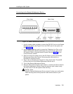
Connect the other end of the cords to extension jacks on 206 module(s) in
the communications system control unit. Refer to the PARTNER MAIL
column on communications system Planning Form B1 for extension
assignments.
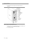
3. Set the voltage selector switch to the appropriate voltage, 115V or 230V.
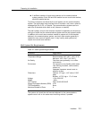
Bracket
Lip
Captive
Retaining
Screw
Mounting
Hole
Power
Supply
Vents
(Do not block)
Voltage
Selector
Figure 2-4. System Unit (Back and Left Side View)
Installation
2-7