


Putting the System Unit Back Together
Putting the System Unit Back Together
1.
2.
3.
4.
5.
6.
7.
8.
9.
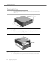
Replace the cover, first lowering it over the chassis and then sliding it
forward to engage the slip-clasp (see Figure 7-4).
Tighten the four cover screws (see Figure 7-3).
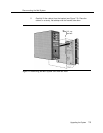
Lift the cabinet and securely position it on the bracket, placing the
cabinet’s bracket lip into the hanger slot on the bracket (see Figure 7-2).
Tighten the captive retaining screw on the bracket into the mounting hole
on the cabinet (see Figure 7-1).
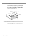
Reconnect the modular telephone cords to the correct mail system ports.
Reconnect the modem cable to the COM 1 port.
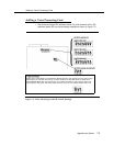
Route the new telephone cords through the slots on the bracket and
connect them to the appropriate ports on the new voice processing card.
Connect the other end of the telephone cords to the appropriate
extension jacks on 206 modules in the communications system control
unit. Refer to communications system Planning Form B1 for proper
extension assignments.
Program the extensions connected to the new mail system ports. See
Chapters 3 and 4 for instructions.
a.
b.
c.
d.
Add the new extensions to the VMS Hunt Group, using Hunt
Group Extensions (#505).
If the new extensions are Pooled extensions, use Line Access
Mode (#313) to change them to Key extensions.
Use Transfer Return Extension (#306) to identify where
unanswered transferred calls from the new extensions should go,
typically extension 10.
Restrict the new extensions using Outgoing Call Restriction (#401).
■
If Outcalling is not permitted, the extensions should be
restricted to Inside Only.
■
If Outcalling is permitted, Outgoing Call Restriction should
be used with Allowed and Disallowed Lists to meet the
needs of the business while maintaining the security of the
system.
Upgrading the System
7-7