RL78/G1A CHAPTER 29 ELECTRICAL SPECIFICATIONS (T
A = −40 to +85°C)
R01UH0305EJ0200 Rev.2.00 881
Jul 04, 2013
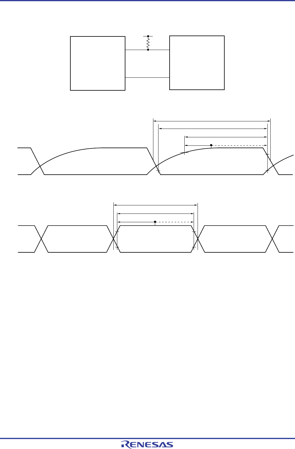
UART mode connection diagram (during communication at different potential)
RL78
microcontroller
TxDq
RxDq
Rx
Tx
User device
V
b
R
b
UART mode bit width (during communication at different potential) (reference)
Baud rate error tolerance
High-/Low-bit width
1/Transfer rate
Baud rate error tolerance
High-bit width
Low-bit width
1/Transfer rate
TxDq
RxDq
Remarks 1. Rb[Ω]: Communication line (TxDq) pull-up resistance,
C
b[F]: Communication line (TxDq) load capacitance, Vb[V]: Communication line voltage
2. q: UART number (q = 0 to 2), g: PIM and POM number (g = 0, 1)
3. f
MCK: Serial array unit operation clock frequency
(Operation clock to be set by the CKSmn bit of serial mode register mn (SMRmn).
m: Unit number, n: Channel number (mn = 00 to 03, 10, 11))


