RL78/G1A CHAPTER 8 INTERVAL TIMER
CHAPTER 8 12-BIT INTERVAL TIMER
8.1 Functions of 12-bit Interval Timer
An interrupt (INTIT) is generated at any previously specified time interval. It can be utilized for wakeup from STOP
mode and triggering an A/D converter’s SNOOZE mode.
8.2 Configuration of 12-bit Interval Timer
The interval timer includes the following hardware.
Table 8-1. Configuration of 12-bit Interval Timer
Item Configuration
Counter 12-bit counter
Peripheral enable register 0 (PER0)
Subsystem clock supply mode control register (OSMC)
Control registers
Interval timer control register (ITMC)
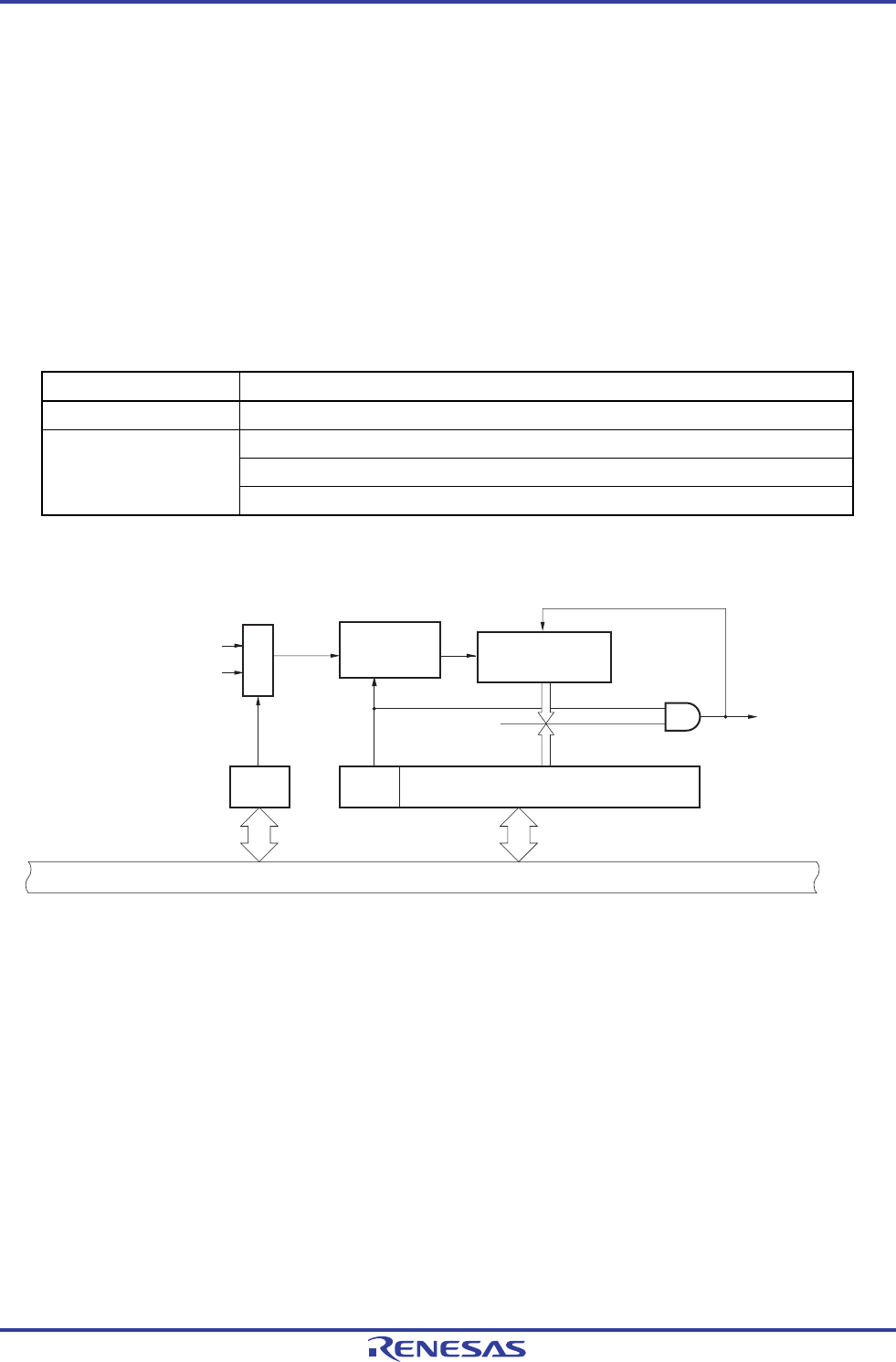
Figure 8-1. Block Diagram of 12-bit Interval Timer
WUTMM
CK0
f
SUB
f
IL
RINTE ITCMP11 to ITCMP0
Count
clock
12-bit counter
Clear
Subsystem clock supply
mode control register (OSMC)
Interval timer control
register (ITMC)
Interrupt request
signal (INTIT)
Count
operation
controller
Selector
Match signal
Internal bus
<R>
Caution The subsystem clock (fSUB) is selectable as a count clock in the 48- and 64-pin products.
<R>
R01UH0305EJ0200 Rev.2.00 321
Jul 04, 2013


