RL78/G1A CHAPTER 16 INTERRUPT FUNCTIONS
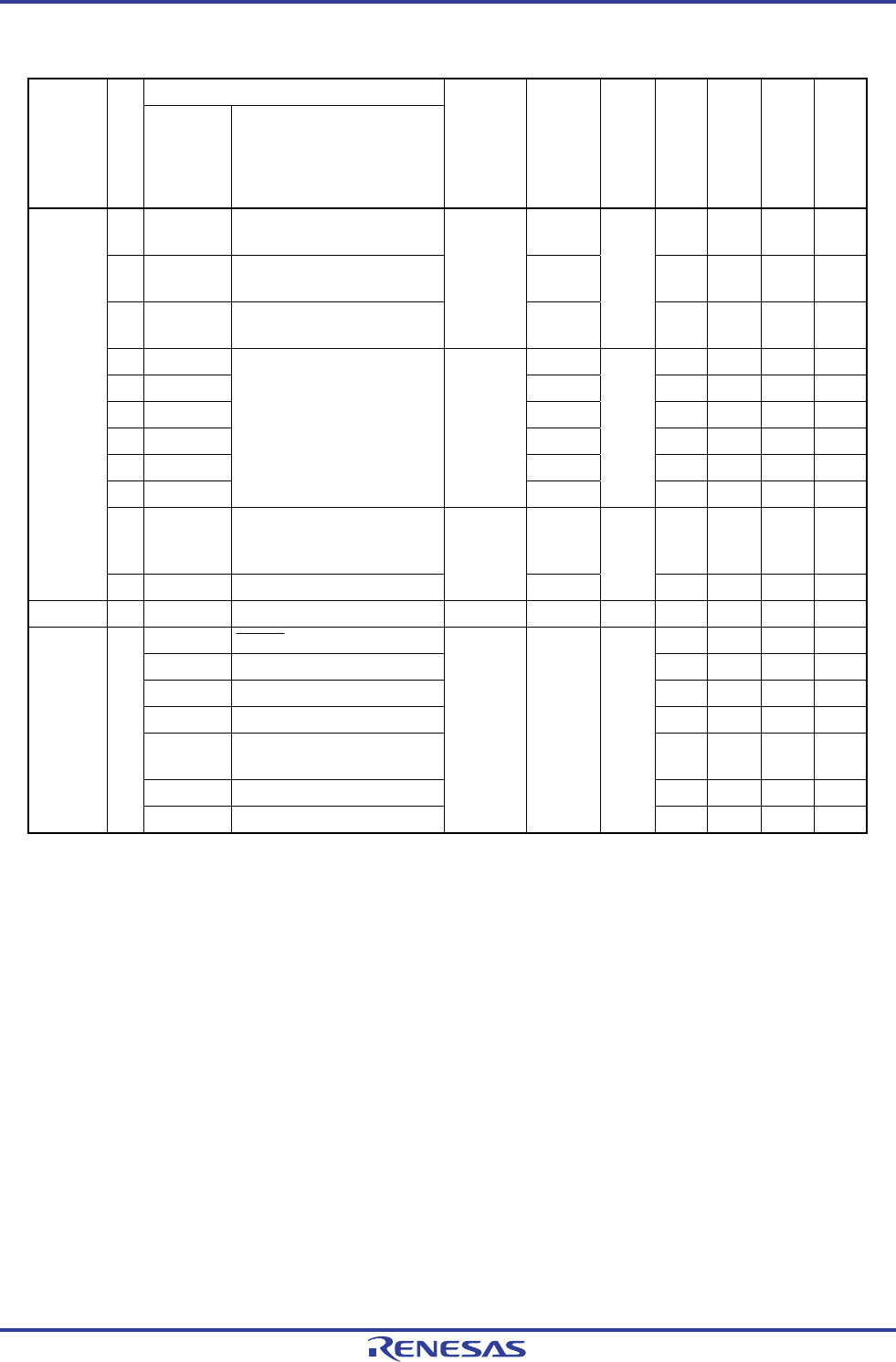
Table 16-1. Interrupt Source List (3/3)
Interrupt Source
Interrupt
Type
Default Priority
Note 1
Name Trigger
Internal/
External
Vector
Table
Address
Basic
Configuration
Type
Note 2
64-pin 48-pin 32-pin 25-pin
29 INTTM05 End of timer channel 5 count
or capture
0044H √ √ √ √
30 INTTM06 End of timer channel 6 count
or capture
0046H √ √ √ √
31 INTTM07 End of timer channel 7 count
or capture
Internal
0048H
(A)
√ √ √ √
32 INTP6 004AH √ √ − −
33 INTP7 004CH √ − − −
34 INTP8 004EH √ √ − −
35 INTP9 0050H √ √ − −
36 INTP10 0052H √ − − −
37 INTP11
Pin input edge detection External
0054H
(B)
√ − − −
38 INTMD End of division operation/
Overflow of multiply-
accumulation result occurs
005EH √ √ √ √
Maskable
39 INTFL Reserved
Note 3
Internal
0062H
(A)
√ √ √ √
Software − BRK Execution of BRK instruction − 007EH (D) √ √ √ √
RESET RESET pin input √ √ √ √
POR Power-on-reset √ √ √ √
LVD Voltage detection
Note 3
√ √ √ √
WDT Overflow of watchdog timer √ √ √ √
TRAP Execution of illegal
instruction
Note 4
√ √ √ √
IAW Illegal-memory access √ √ √ √
Reset −
RPE RAM parity error
− 0000H −
√ √ √ √
<R>
<R>
Notes 1. The default priority determines the sequence of interrupts if two or more maskable interrupts occur
simultaneously. Zero indicates the highest priority and 39 indicates the lowest priority.
2. Basic configuration types (A) to (D) correspond to (A) to (D) in Figure 16-1.
<R>
3. Be used at the flash self programming library or the data flash library.
4. When bit 7 (LVIMD) of the voltage detection level register (LVIS) is set to 1.
5. When the instruction code in FFH is executed.
Reset by the illegal instruction execution not issued by emulation with the in-circuit emulator or on-chip
debug emulator.
R01UH0305EJ0200 Rev.2.00 691
Jul 04, 2013


