RL78/G1A CHAPTER 13 SERIAL INTERFACE IICA
13.5 I
2
C Bus Definitions and Control Methods
The following section describes the I
2
C bus’s serial data communication format and the signals used by the I
2
C bus.
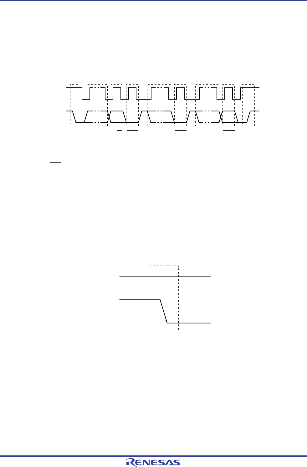
Figure 13-14 shows the transfer timing for the “start condition”, “address”, “data”, and “stop condition” output via the I
2
C
bus’s serial data bus.
Figure 13-14. I
2
C Bus Serial Data Transfer Timing
SCLA0
SDAA0
Start
condition
Address R/W ACK
Data
1-7 8 9 1-8
ACK Data ACK Stop
condition
9 1-8 9
The master device generates the start condition, slave address, and stop condition.
The acknowledge (ACK) can be generated by either the master or slave device (normally, it is output by the device that
receives 8-bit data).
The serial clock (SCLA0) is continuously output by the master device. However, in the slave device, the SCLA0 pin low
level period can be extended and a wait can be inserted.
13.5.1 Start conditions
A start condition is met when the SCLA0 pin is at high level and the SDAA0 pin changes from high level to low level.
The start conditions for the SCLA0 pin and SDAA0 pin are signals that the master device generates to the slave device
when starting a serial transfer. When the device is used as a slave, start conditions can be detected.
Figure 13-15. Start Conditions
SCLA0
SDAA0
H
A start condition is output when bit 1 (STT0) of IICA control register 00 (IICCTL00) is set (1) after a stop condition has
been detected (SPD0: Bit 0 of the IICA status register 0 (IICS0) = 1). When a start condition is detected, bit 1 (STD0) of
the IICS0 register is set (1).
R01UH0305EJ0200 Rev.2.00 590
Jul 04, 2013


