RL78/G1A CHAPTER 13 SERIAL INTERFACE IICA
(2) Master operation in multi-master system
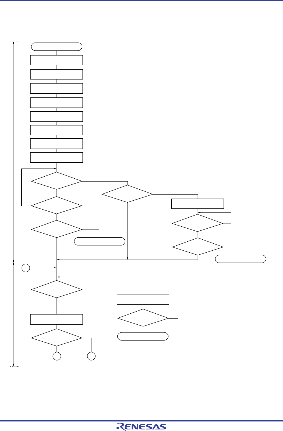
Figure 13-29. Master Operation in Multi-Master System (1/4)
IICWLn, IICWHn ← XXH
IICFn ← 0XH
Setting STCENn and IICRSVn
Setting port
Setting IICCTLn1
SPTn = 1
SVAn ← XXH
SPIEn = 1
START
Slave operation
Slave operation
Releases the bus for a specific period.
Bus status is
being checked.
Yes
Checking bus status
Note
Master operation
starts?
Enables reserving
communication.
Disables reserving
communication.
SPDn = 1?
STCENn = 1?
IICRSVn = 0?
A
Selects a transfer clock.
Sets a local address.
Sets a start condition.
(Communication start request)
(No communication start request)
• Waiting to be specified as a slave by other master
• Waiting for a communication start request (depends on user program)
Prepares for starting
communication
(generates a stop condition).
Waits for detection
of the stop condition.
No
Yes
Yes
No
INTIICAn
interrupt occurs?
INTIICAn
interrupt occurs?
Yes
No
Yes
No
SPDn = 1?
Yes
No
Slave operation
No
INTIICAn
interrupt occurs?
Yes
No
1
B
SPIEn = 0
Yes
No
Waits for a communication request.
Waits for a communication Initial setting
IICCTLn0 ← 1XX111XXB
IICEn = 1
IICCTLn0 ← 0XX111XXB
ACKEn = WTIMn = SPIEn = 1
Setting of the port used alternatively as the pin to be used.
First, set the port to input mode and the output latch to 0 (see 13.3.8 Port mode register 6 (PM6)).
Setting port
Set the port from input mode to output mode and enable the output of the I
2
C bus
(see 13.3.8 Port mode register 6 (PM6)).
<R>
Note Confirm that the bus is released (CLD0 bit = 1, DAD0 bit = 1) for a specific period (for example, for a period of
one frame). If the SDAA0 pin is constantly at low level, decide whether to release the I
2
C bus (SCLA0 and
SDAA0 pins = high level) in conformance with the specifications of the product that is communicating.
Remark n = 0
R01UH0305EJ0200 Rev.2.00 611
Jul 04, 2013


