RL78/G1A CHAPTER 5 CLOCK GENERATOR
R01UH0305EJ0200 Rev.2.00 179
Jul 04, 2013
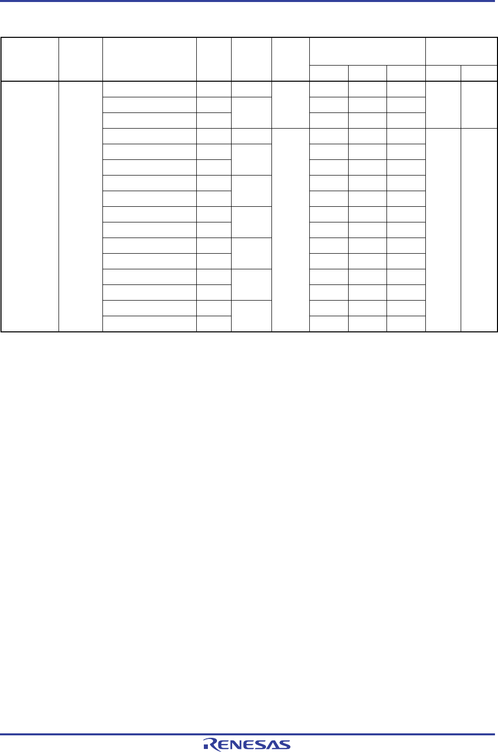
(1) X1 oscillation: As of February, 2013 (1/3)
Recommended Circuit
Constants
Note 3
(reference)
Oscillation Voltage
Range (V)
Manufacturer Resonator Part Number
Note 1
SMD/
Lead
Frequency
(MHz)
Flash
operation
mode
Note 2
C1 (pF) C2 (pF) Rd (kΩ) MIN. MAX.
CSTCC2M00G56-R0 SMD 2.0 (47) (47) 0
CSTCR4M00G55-R0 SMD (39) (39) 0
CSTLS4M00G53-B0 Lead
4.0
LV
(15) (15) 0
1.6 3.6
CSTCC2M00G56-R0 SMD 2.0 (47) (47) 0
CSTCR4M00G55-R0 SMD (39) (39) 0
CSTLS4M00G53-B0 Lead
4.0
(15) (15) 0
CSTCR4M19G55-R0 SMD (39) (39) 0
CSTLS4M19G53-B0 Lead
4.194
(15) (15) 0
CSTCR4M91G53-R0 SMD (15) (15) 0
CSTLS4M91G53-B0 Lead
4.915
(15) (15) 0
CSTCR5M00G53-R0 SMD (15) (15) 0
CSTLS5M00G53-B0 Lead
5.0
(15) (15) 0
CSTCR6M00G53-R0 SMD (15) (15) 0
CSTLS6M00G53-B0 Lead
6.0
(15) (15) 0
CSTCE8M00G52-R0 SMD (10) (10) 0
Murata
Manufacturing
Co., Ltd.
Note 4
Ceramic
resonator
CSTLS8M00G53-B0 Lead
8.0
LS
(15) (15) 0
1.8 3.6
Notes 1. The part numbers of the products that can operate at up to 105°C differ from those listed in the above table. For
details, contact Murata Manufacturing Co., Ltd.
2. Set the flash operation mode by using CMODE1 and CMODE0 bits of the option byte (000C2H/010C2H).
3. Values in parentheses in the C1, C2 columns indicate an internal capacitance.
4. When using these oscillators, contact Murata Manufacturing Co., Ltd. (http://www.murata.com/index.html).
Remark Relationship between operation voltage width, operation frequency of CPU and operation mode is as below.
HS (High speed main) mode: 2.7 V ≤ V
DD ≤ 3.6 V@1 MHz to 32 MHz (When X1 oscillation: 1 MHz to 20 MHz)
2.4 V ≤ V
DD ≤ 3.6 V@1 MHz to 16 MHz
LS (Low speed main) mode: 1.8 V ≤ V
DD ≤ 3.6 V@1 MHz to 8 MHz
LV (Low voltage main) mode: 1.6 V ≤ VDD ≤ 3.6 V@1 MHz to 4 MHz


