RL78/G1A CHAPTER 17 KEY INTERRUPT FUNCTION
17.3.3 Key return flag register (KRF)
This register controls the key interrupt flags (KRF0 to KRF5).
The KRF register can be set by a 1-bit or 8-bit memory manipulation instruction.
Reset signal generation clears this register to 00H.
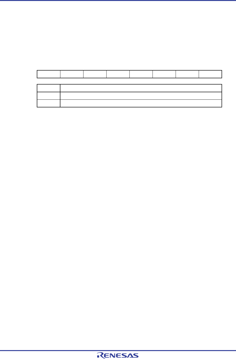
Figure 17-4. Format of Key return Flag Register (KRF)
Address: FFF35H After reset: 00H R/W
Note
Symbol 7 6 5 4 3 2 1 0
KRF 0 0 KRF5 KRF4 KRF3 KRF2 KRF1 KRF0
KRFn Key interrupt flag
0 No key interrupt signal has been detected.
1 A key interrupt signal has been detected.
Note Writing to 1 is invalid. To clear KRFn, write “0” to the target bits and write “1” to other bits, with the 8-bit memory
manipulation instruction.
Caution For KR6 to KR9, identify channels by sequentially verifying the input levels.
Remark n = 0 to 5
R01UH0305EJ0200 Rev.2.00 719
Jul 04, 2013


