RL78/G1A CHAPTER 17 KEY INTERRUPT FUNCTION
17.3 Register Controlling Key Interrupt
The key interrupt function is controlled by the following five registers:
• Key return control register (KRCTL)
• Key return mode registers 0, 1 (KRM0, KRM1)
• Key return flag register (KRF)
• Port mode registers 0 to 2, 7, 12, and 15 (PM0 to PM2, PM7, PM12, PM15)
• Peripheral I/O redirection register (PIOR)
17.3.1 Key return control register (KRCTL)
This register controls the usage of the key interrupt flags (KRF0 to KRF5) and sets the detection edge.
The KRCTL register can be set by a 1-bit or 8-bit memory manipulation instruction.
Reset signal generation sets this register to 00H.
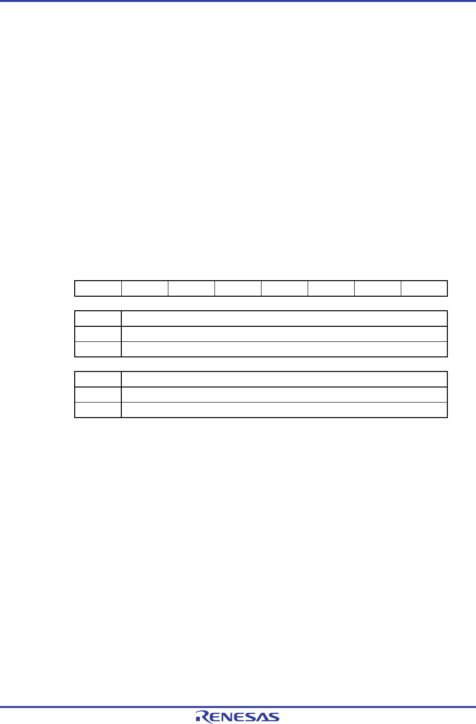
Figure 17-2. Format of Key Return Control Register (KRCTL)
Address: FFF34H After reset: 00H R/W
Symbol 7 6 5 4 3 2 1 0
KRCTL KRMD 0 0 0 0 0 0 KREG
KRMD Usage of t key interrupt flags (KRF0 to KRF5)
0 Does not use key interrupt flags
1 Uses key interrupt flags
KREG Selection of detection edge (KR0 to KR9)
0 Falling edge
1 Rising edge
R01UH0305EJ0200 Rev.2.00 717
Jul 04, 2013


