RL78/G1A CHAPTER 13 SERIAL INTERFACE IICA
13.3.6 IICA low-level width setting register 0 (IICWL0)
This register is used to control the low-level width (tLOW) of the SCLA0 pin signal that is output by serial interface IICA
and the SDAA0 pin signal.
The IICWL0 register can be set by an 8-bit memory manipulation instruction.
Set the IICWL0 register while operation of I
2
C is disabled (bit 7 (IICE0) of IICA control register 00 (IICCTL00) is 0).
Reset signal generation sets this register to FFH.
For details about setting the IICWL0 register, see 13.4.2 Setting transfer clock by using IICWL0 and IICWH0
registers.
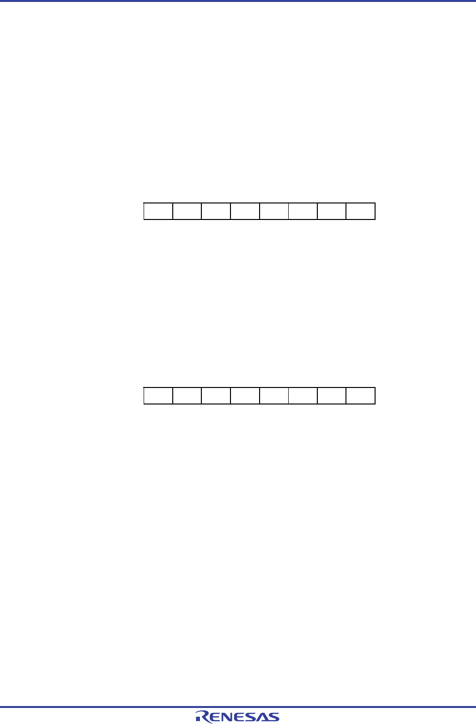
Figure 13-10. Format of IICA Low-Level Width Setting Register 0 (IICWL0)
Address: F0232H After reset: FFH R/W
Symbol 7 6 5 4 3 2 1 0
IICWL0
13.3.7 IICA high-level width setting register 0 (IICWH0)
This register is used to control the high-level width of the SCLA0 pin signal that is output by serial interface IICA and the
SDAA0 pin signal.
The IICWH0 register can be set by an 8-bit memory manipulation instruction.
Set the IICWH0 register while operation of I
2
C is disabled (bit 7 (IICE0) of IICA control register 00 (IICCTL00) is 0).
Reset signal generation sets this register to FFH.
Figure 13-11. Format of IICA High-Level Width Setting Register 0 (IICWH0)
Address: F0233H After reset: FFH R/W
Symbol 7 6 5 4 3 2 1 0
IICWH0
Remark For setting procedures of the transfer clock on master side and of the IICWL0 and IICWH0
registers on slave side, see 13.4.2 (1) and 13.4.2 (2), respectively.
<R>
R01UH0305EJ0200 Rev.2.00 585
Jul 04, 2013


