


NDA-24282 CHAPTER 4
Page 65
Revision 1.0
PH-PC21 (APINT)
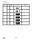
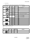
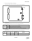
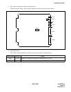
3. Face Layout of Lamps, Switches, and Connectors
The face layout of lamps, switches, and connectors of this circuit card is shown below.
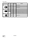
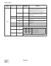
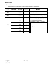
4. Lamp Indications
The contents of lamp indications of this circuit card are shown in the table below.
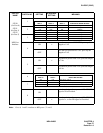
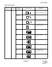
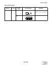
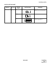
5. Switch Settings
Standard settings of various switches on this circuit card are shown in the table below.
LAMP NAME COLOR STATE
OPE/MB
Green Remains lit while this circuit card is operating.
Red Lights while this circuit card is in make-busy state.
CLKALM Red Lights when a failure has occurred to clocks for I/O bus synchronization.
SWITCH
NAME
SWITCH NO. SETTING
STANDARD
SETTING
MEANING
MB
UP Circuit card make busy.
DOWN Circuit card make idle.
CLKALM
OPE/MB
MB
SW01
AP0
AP1