


NDA-24282 (E) CHAPTER 9
Page 449
Revision 1.0
SYSTEM MAINTENANCE
4.2 DIAGNOSTICS FROM SYSTEM MESSAGES
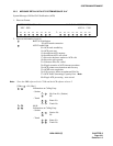
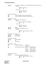
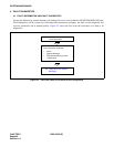
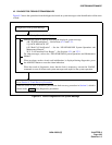
Figure 9-3 shows the operations from the diagnostics based on system messages to the identification of the cause
of fault.
Figure 9-3 Flow of Diagnostics from System Message
Diagnostics from System Message
Determination of Faulty Circuit Card or Equipment
Identifies the cause of fault by analyzing the displayed system message
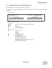
4-R “TCP/IP Link Failure” – See Sections 4.2.1 and 3.2.1.
5-Q “ACD MIS LOCK UP”
6-H “Bad Call Notification” – See the “NEAX2400 IMX System Operations and
Maintenance Manual”.
26-V “LAN interface Error Report” – See Sections 4.2.1 and 3.2.3.
For other messages, refer to the “NEAX2400 IMX System Operations and Maintenance
Manual”.
When an alarm, such as circuit card initialization, is displayed during diagnostics, press
the ALM RST button to reset the alarm indication.
When the result of diagnostics shows that the fault is temporary, execute the “RALM”
command to reset all alarms and system messages and supervise the system operation.
Go to Section 5, “Fault Recovery Procedure”
When the cause of fault is identified, perform the fault recovery procedure in Section 5, which is
shown inside of the diagnostics procedures.