


NDA-24282 (E) CHAPTER 4
Page 147
Revision 1.0
PA-4DATB (DAT)
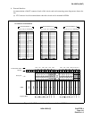
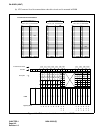
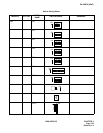
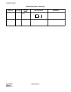
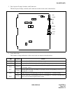
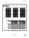
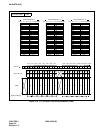
3. Face Layout of Lamps, Switches, and Connectors
The face layout of lamps, switches, and connectors on this circuit card is shown below.
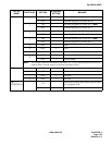
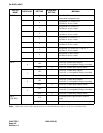
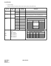
4. Lamp Indications
The contents of lamp indications of this circuit card are shown in the table below.
LAMP COLOR STATE
OPE Green Remains lit while this circuit card is operating.
N-OPE Red Remains lit while this circuit card is in make-busy state.
BL4
BL7
Green
Lights when the corresponding circuit (No 0 through No. 3 circuits) is connected to
a recording source.
Flash
Flashes while message recording is in progress on the corresponding circuit (No. 0
through No. 3 circuit).
BL0
BL3
Red Lights when the corresponding circuit (No. 0 through No. 3 circuits) is busy.
Flash
Flashes when the corresponding circuit (No. 0 through No. 3 circuits) is in make-busy
state or has not been assigned in the system.
OPE
N-OPE
MB
ML7
ML0
START
3
2
1
0
SW1
SW5
SW6
SW4
JP0
MB RQ
MRCS
JACK
WR
SW3
SW7
SW2
~~