


CHAPTER 4 NDA-24282 (E)
Page 138
Revision 1.0
PA-4DATA (4DAT)
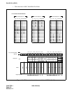
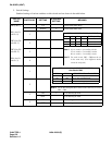
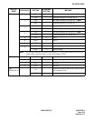
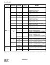
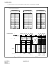
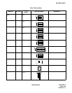
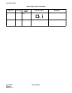
5. Switch Settings
Standard settings of various switches on this circuit card are shown in the table below.
SWITCH
NAME
SWITCH NO. SETTING
STANDARD
SETTING
MEANING
MB (SW11) UP Circuit card make busy.
DOWN × Circuit card make idle.
SW1 (for Cir-
cuit No. 0
)
1
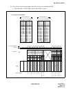
SW2 (for Cir-
cuit No. 1)
2
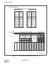
SW3 (for Cir-
cuit No. 2)
3
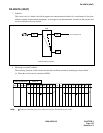
Note 1: 16-sec. mode = 4 recording circuits
32-sec. mode = 2 recording circuits
60-sec. mode = 1 recording circuit.
Note 2: For each circuit, SW1 ~ SW4 must be set
in the same way. (Two different modes
cannot be assigned.)
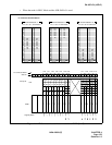
SW4 (for Cir-
cuit No. 3
)
4
SW5
1
2
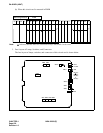
Note 3: Set the Recording/Playback Timer in the same way as set by
SW1 ~ SW4.
3
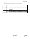
ON × To be used by µ-Law.
OFF To be used by Α-Law.
4
ON When using as an external hold tone source
OFF When using as announcement equipment only
SETTING OF TIMER FOR EACH CIRCUIT
1 2 3 4 TIMER (MODE)
ON ON OFF ON 16-sec. mode
ON ON ON OFF 32-sec. mode
OFF OFF OFF OFF 60-sec. mode
SETTING OF ANNOUNCEMENT RECORDING/
PLAYBACK TIME
SW5-1 SW5-2 RECORDING/PLAYBACK TIME
OFF ON 16-sec. Recording/Playback
ON OFF 32-sec. Recording/Playback
OFF OFF 60-sec. Recording/Playback