


NDA-24282 (E) CHAPTER 4
Page 157
Revision 1.0
PA-4DTLA (4DTL)
4. Lamp Indications
The contents of lamp indications of this circuit card are shown in the table below.
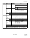
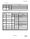
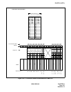
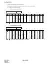
5. Switch Settings
Standard settings of various switches on this circuit card are shown in the table below.
LAMP NAME COLOR Status STATE
OPE Green ON The Port Microprocessor is operating normally.
N-OPE Red ON The Port Microprocessor is not operating due to MB switch or software.
BL0
BL3
Red
ON The circuit is in use.
Blinking
(1/sec.)
The circuit is out of service due to switch setting or software.
SWITCH
TYPE AND
NAME
FUNCTION
SWITCH
ELEMENT POSITION MEANING
Toggle Switch
MB
Make Busy (entire
circuit card)
UP Take circuit card out of service.
DOWN Normal operation.
“Piano” keys
MB0 ~ MB3
Busy out individual
circuits
0 ~ 3
UP (left) Normal operation.
DOWN (right)
Take corresponding circuit out of ser-
vice.
Dip Switch
SW0
1 ~ 4 Must be ON
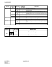
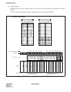
DIP Switch
RFBS
Received framing bit
control
1 ~ 4
Note
ON Firmware control; DSR always ON.
OFF
Hardware control; DSR set by DTE
(standard setting).
DIP Switch
SFBS
Sent framing bit
control
1 ~ 4
Note
ON Firmware control; DSR always ON.
OFF
Hardware control; DSR set by DTE
(standard setting).
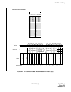
DIP Switch
RSBS
Not used 1 ~ 4 OFF
(Standard setting.)
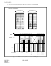
DIP Switch
ECSL
Not used 1 ~ 4 OFF
(Standard setting.)
Note:
Each switch element (1 ~ 4) controls the corresponding circuit (0 ~ 3).
~