


LIST OF FIGURES
Figure Title Page
NDA-24282 LIST OF FIGURES
Page vii
Revision 1.0
Figure 2-1 Functional Outline of NEAX2400 CallCenterWorX-Enterprise ACD System . . . . . . . . . . . . . 4
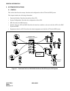
Figure 2-2 Block Diagram of ACD System (Single CPU Configuration) . . . . . . . . . . . . . . . . . . . . . . . . . . 7
Figure 2-3 Block Diagram of ACD System (Dual CPU Configuration) . . . . . . . . . . . . . . . . . . . . . . . . . . . 8
Figure 2-4 Outer View of Dterm Series III Agent Position . . . . . . . . . . . . . . . . . . . . . . . . . . . . . . . . . . . 11
Figure 2-5 Over View of Dterm Series E Agent Position . . . . . . . . . . . . . . . . . . . . . . . . . . . . . . . . . . . . 12
Figure 2-6 Supervisory Positions . . . . . . . . . . . . . . . . . . . . . . . . . . . . . . . . . . . . . . . . . . . . . . . . . . . . . . 13
Figure 2-7 NEAX2400 CallCenterWorX-Enterprise ACD System Configuration . . . . . . . . . . . . . . . . . . 14
Figure 2-8 ACD Group Configuration . . . . . . . . . . . . . . . . . . . . . . . . . . . . . . . . . . . . . . . . . . . . . . . . . . . 15
Figure 2-9 Concept of Operation Mode . . . . . . . . . . . . . . . . . . . . . . . . . . . . . . . . . . . . . . . . . . . . . . . . . 17
Figure 3-1 Static Caution Indication . . . . . . . . . . . . . . . . . . . . . . . . . . . . . . . . . . . . . . . . . . . . . . . . . . . . 19
Figure 3-2 3M Model 8012 Portable Field Service Kit . . . . . . . . . . . . . . . . . . . . . . . . . . . . . . . . . . . . . . 20
Figure 3-3 Peripheral Equipment Installation Procedures . . . . . . . . . . . . . . . . . . . . . . . . . . . . . . . . . . . 21
Figure 3-4 Connection of ACD Agent Position . . . . . . . . . . . . . . . . . . . . . . . . . . . . . . . . . . . . . . . . . . . . 22
Figure 3-5 Key Pads on ACD Agent Position Keyboard (Dterm Series III) . . . . . . . . . . . . . . . . . . . . . . 23
Figure 3-6 Key Pads on ACD Agent Position Keyboard (Dterm Series E) . . . . . . . . . . . . . . . . . . . . . . . 24
Figure 3-7 Connection of ACD Supervisory Position . . . . . . . . . . . . . . . . . . . . . . . . . . . . . . . . . . . . . . . 25
Figure 3-8 Key Pads on Supervisory Position Keyboard (Dterm Series III) . . . . . . . . . . . . . . . . . . . . . . 26
Figure 3-9 Key Pads on Supervisory Position Keyboard (Dterm Series E) . . . . . . . . . . . . . . . . . . . . . . 27
Figure 3-10 Cable Connection between MIS and PBX . . . . . . . . . . . . . . . . . . . . . . . . . . . . . . . . . . . . . . 28
Figure 3-11 Connection of Emergency Recorder (When Emergency Recorder Has Starting Terminal) 29
Figure 3-12 Connection of Emergency Recorder (When Emergency Recorder Does Not Have
Starting Terminal) . . . . . . . . . . . . . . . . . . . . . . . . . . . . . . . . . . . . . . . . . . . . . . . . . . . . . . . . . 29
Figure 3-13 Connection of Announcement Machine . . . . . . . . . . . . . . . . . . . . . . . . . . . . . . . . . . . . . . . . 30
Figure 3-14 System Configuration (when IVR/Host is installed) . . . . . . . . . . . . . . . . . . . . . . . . . . . . . . . 31
Figure 3-15 Connection of Host . . . . . . . . . . . . . . . . . . . . . . . . . . . . . . . . . . . . . . . . . . . . . . . . . . . . . . . . 32
Figure 3-16 Connection of IVR . . . . . . . . . . . . . . . . . . . . . . . . . . . . . . . . . . . . . . . . . . . . . . . . . . . . . . . . . 33
Figure 3-17 Hardware and Software Upgrading Requirements . . . . . . . . . . . . . . . . . . . . . . . . . . . . . . . . 37
Figure 4-1 RS Connector Leads Accommodation . . . . . . . . . . . . . . . . . . . . . . . . . . . . . . . . . . . . . . . . . 88
Figure 4-2 Position in IMG
dxh
. . . . . . . . . . . . . . . . . . . . . . . . . . . . . . . . . . . . . . . . . . . . . . . . . . . . . . . . 95
Figure 4-3 LT Connector Leads Accommodation of PIMU-A (1/2) . . . . . . . . . . . . . . . . . . . . . . . . . . . . 103
Figure 4-3 LT Connector Leads Accommodation of PIMU-A (2/2) . . . . . . . . . . . . . . . . . . . . . . . . . . . . 104
Figure 4-4 LT Connector Leads Accommodation of PIMB (1/2) . . . . . . . . . . . . . . . . . . . . . . . . . . . . . 105
Figure 4-4 LT Connector Leads Accommodation of PIMB (2/2) . . . . . . . . . . . . . . . . . . . . . . . . . . . . . 106
Figure 4-5 ELC Connector Leads Accommodation of PIMB (1/2) . . . . . . . . . . . . . . . . . . . . . . . . . . . . 107
Figure 4-5 ELC Connector Leads Accommodation of PIMB (2/2) . . . . . . . . . . . . . . . . . . . . . . . . . . . . 108
Figure 4-6 Connection Diagram . . . . . . . . . . . . . . . . . . . . . . . . . . . . . . . . . . . . . . . . . . . . . . . . . . . . . . 109
Figure 4-7 LT Connector Leads Accommodation of PIMU-A (1 of 3) . . . . . . . . . . . . . . . . . . . . . . . . . . 116
Figure 4-7 LT Connector Leads Accommodation of PIMU-A (2 of 3) . . . . . . . . . . . . . . . . . . . . . . . . . . 117
Figure 4-7 LT Connector Leads Accommodation of PIMU-A (3 of 3) . . . . . . . . . . . . . . . . . . . . . . . . . . 118
Figure 4-8 LT Connector Leads Accommodation of PIMB (1 of 3) . . . . . . . . . . . . . . . . . . . . . . . . . . . 119
Figure 4-8 LT Connector Leads Accommodation of PIMB (2 of 3) . . . . . . . . . . . . . . . . . . . . . . . . . . . 120
Figure 4-8 LT Connector Leads Accommodation of PIMB (3 of 3) . . . . . . . . . . . . . . . . . . . . . . . . . . . 121
Figure 4-9 Connecting Route Diagram . . . . . . . . . . . . . . . . . . . . . . . . . . . . . . . . . . . . . . . . . . . . . . . . . 122
Figure 4-10 LT Connector Leads Accommodation of PIMU-A (1 of 3) . . . . . . . . . . . . . . . . . . . . . . . . . . 128
Figure 4-10 LT Connector Lead Accommodation of PIMU-A (2 of 3) . . . . . . . . . . . . . . . . . . . . . . . . . . 129
Figure 4-10 LT Connector Leads Accommodation of PIMU-A (3 of 3) . . . . . . . . . . . . . . . . . . . . . . . . . . 130
Figure 4-11 LT Connector Leads Accommodation of PIMK (1 of 3) . . . . . . . . . . . . . . . . . . . . . . . . . . . 131
Figure 4-11 LT Connector Leads Accommodation of PIMK (2 of 3) . . . . . . . . . . . . . . . . . . . . . . . . . . . 132