


NDA-24282 CHAPTER 3
Page 31
Revision 1.0
INSTALLATION
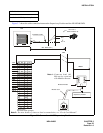
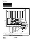
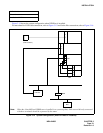
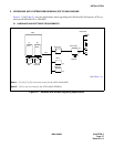
Figure 3-14 shows the system configuration when IVR/Host is installed.
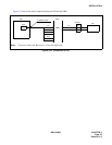
For more details of IVR cable connection, refer to Figure 3-15 and for the Host connection, refer to Figure 3-16.
Figure 3-14 System Configuration (when IVR/Host is installed)
NAP-200-106
Sheet 1/1
Installation of IVR/Host
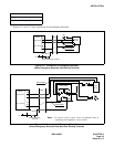
Note:
When the client MIS and IVR/Host are installed in a system together, LAN network directly connected
with these terminals should be separated by the router.
Router
MIS
IVR/Host
D
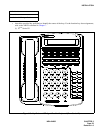
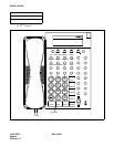
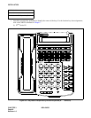
term
(ACD Positions)
E
L
C
L
C
HUB
PBX
L
A
N
L
A
N
Note