


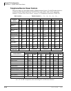
Strata CTX Configuration
Reserve Power (CTX100 and CTX670)
2-48 Strata CTX I&M 06/04
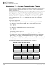
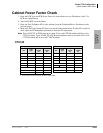
Determine CTX670 system miscellaneous power components in the following worksheet. (See
Tables 2-63 and 2-66 for component descriptions.) These components are not used on CTX100
systems.
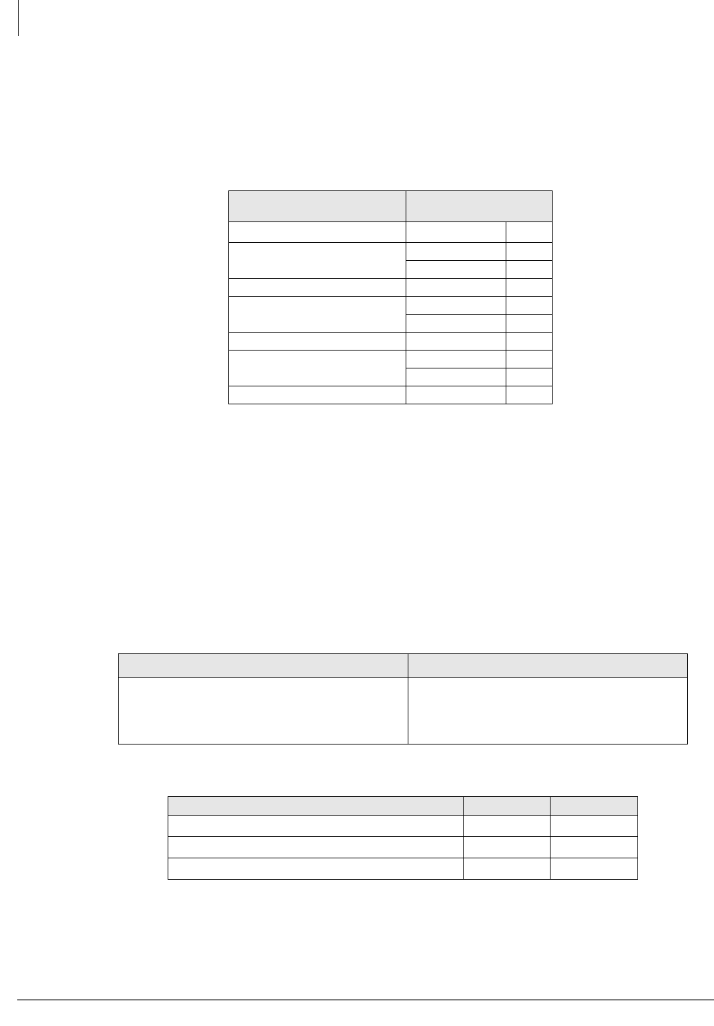
Enter the number of cabinet power components needed:
Reserve Power (CTX100 and CTX670)
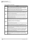
Two or four customer-supplied 12VDC reserve batteries (80 ampere-hours max.) can be connected
to either system to maintain normal operation during a power failure (see Tables 2-61~2-64). The
batteries are kept in a highly-charged state by the power supply’s battery charger and must be
connected when the system is operating normally. Fully charged batteries must be connected when
normal AC power is available, batteries cannot be connected after/during an actual power failure.
The battery changer is standard on the CTX670 power supply. An optional ABCS battery changer
must be used in the CTX100 power supply.
Main Location ____________ Remote Location 1___ 2___ 3___ 4____5___ 6____
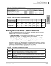
CTX670 Cabinet Power
Components
Enter the Number
Required
Spare Power Supply BPSU672
AC Power Strips
RPSB2
BPSB240
208/240VAC Power Supply Cord BACL240
Battery Cables
PBTC-3M
BBTC1A-2.0M
Battery DIstribution Box BBDB
Conduit Box
BCCB120
BCCB240
Floor Mount Stand BFIF
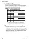
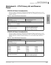
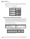
Table 2-61 CTX100 Reserve Power Characteristics
Battery Charger Characteristics Maximum Battery Charger Drain (-24VDC)
Charger: current limiting
Nominal float voltage: 2.275 volts/cell
Charge current: 280mA amps maximum
Battery discharge cut-off voltage: 20.5 ±0.5VDC
Base Cabinet
Base + Expansion Cabinets
3.15 amps
6.30 amps
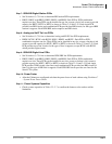
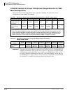
Table 2-62 CTX100 Typical Reserve Power Duration Estimates
1
1. Assumes 80 ampere-hours with 12VDC batteries.
Number of Cabinets 1 2
Estimated operation time Two-battery configuration 25 hr. 12.5 hr.
Estimated operation time Four-battery configuration 50 hr. 25 hr.
DC Current Drain (-24VDC) 3.15 amps. 6.30 amps.