Strata CTX100-S/CTX100 Installation
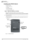
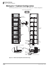
Installing the CTX100 Cabinet
Strata CTX I&M 06/04 3-7
Strata CTX100-S/
CTX100 Installation
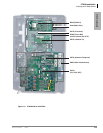
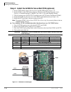
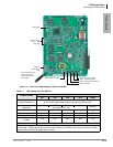
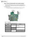
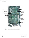
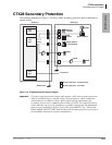
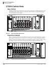
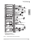
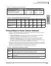
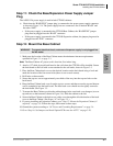
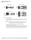
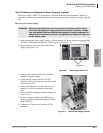
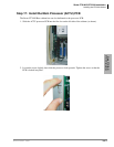
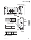
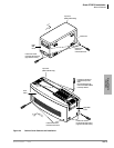
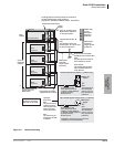
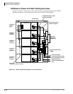
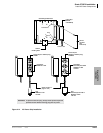
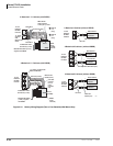
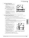
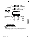
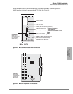
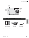
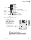
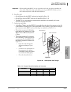
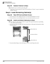
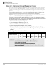
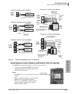
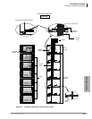
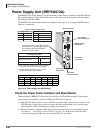
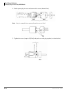
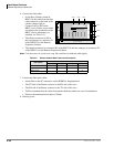
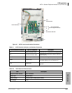
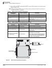
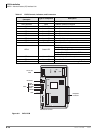
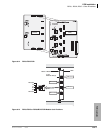
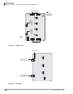
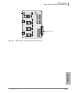
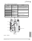
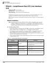
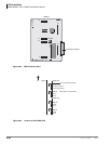
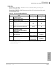
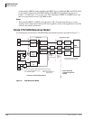
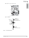
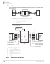
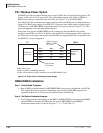
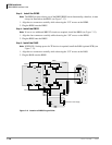
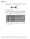
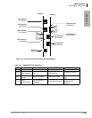
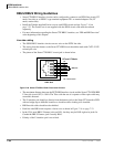
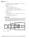
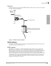
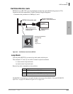
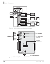
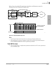
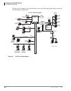
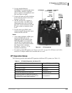
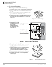
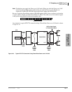
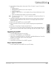
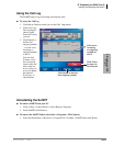
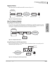
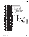
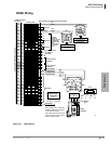
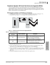
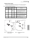
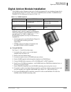
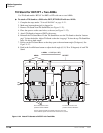
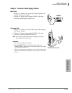
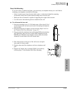
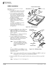
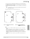
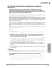
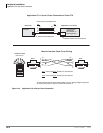
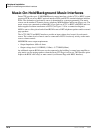
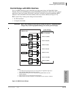
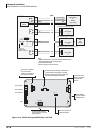
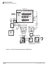
Step 11: Check the Base/Expansion Power Supply Jumper
Plug
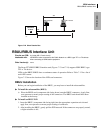
The APSU112A power supply is used in both CTX100 cabinets.
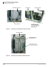
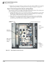
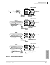
³ Check that the “BASE/EXP.” jumper plug is connected to the proper power supply connector
as shown in Figure 3-14. The power supply has two connectors: one is labeled “BASE” and
the other “EXP.”
• If the power supply is mounted in the CTX100 Base Cabinet, the “BASE/EXP.” jumper
plug must be plugged into the “BASE” connector.
• If the power supply is mounted in the CTX100 Expansion cabinet, the jumper plug must be
plugged into the “EXP.” connector.
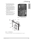
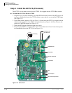
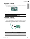
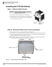
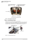
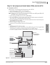
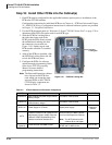
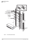
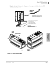
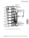
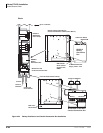
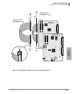
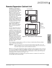
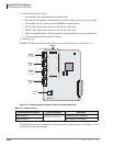
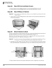
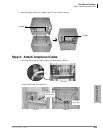
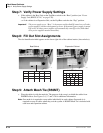
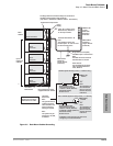
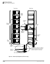
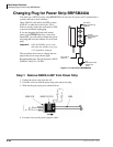
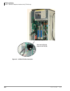
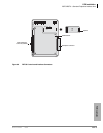
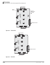
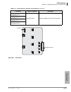
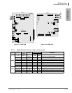
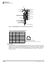
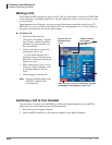
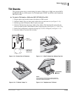
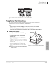
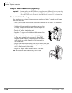
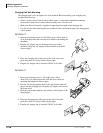
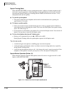
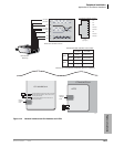
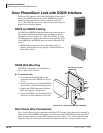
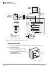
Step 12: Mount the Base Cabinet
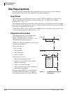
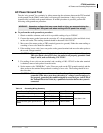
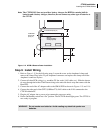
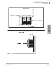
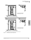
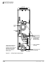
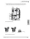
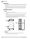
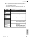
1. Make sure the location of the Base Cabinet meets the minimum clearance requirements
specified in Figure 3-1 on page 3-3.
Note The Base Cabinet AC power cord is four feet, five inches long.
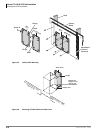
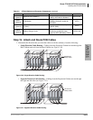
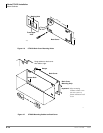
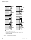
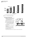
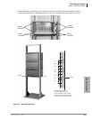
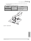
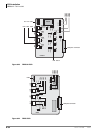
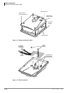
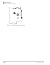
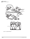
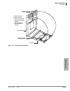
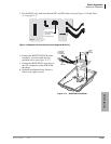
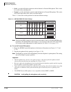
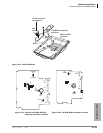
2. Attach a 1/2” thick plywood back board to the wall where the CTX100 will be installed. Secure
the back board to the wall with screws attached to the wall studs, shown in Figure 3-5.
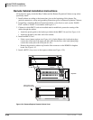
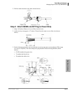
3. Place the Base Cabinet back cover at the desired location on the back board using a level and
mark the location of the four screw holes (there is one on each corner).
4. Drill holes on these marks.
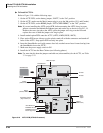
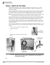
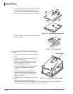
5. Secure the top two screws approximately two thirds of the way into the top two holes on the
back board.
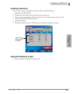
6. Hang the Base Cabinet back cover from the top two screws and then secure the top and bottom
screws completely into the back board. The base back cover should now be tightly secured to
the back board. See Figure 3-5.
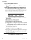
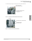
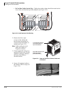
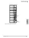
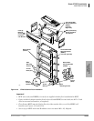
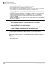
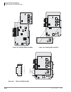
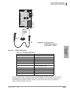
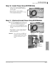
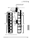
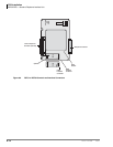
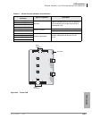
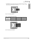
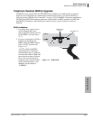
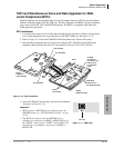
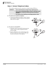
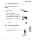
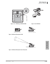
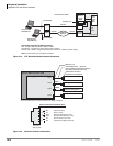
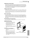
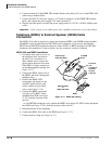
7. To mount the Base Cabinet, position the cabinet hanger holes onto back cover hangers (two on
top and two on the bottom as shown in Figure 3-6). Slide the cabinet to the left.
8. Secure the Base Cabinet to the back cover with a screw through the left side bracket of the back
cover to the Base Cabinet. (See Screw “A” in Figure 3-5.)
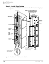
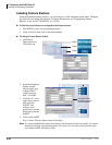
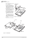
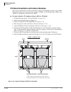
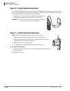
9. If you are installing an Expansion Cabinet, go to “Step 13: Mount the Expansion Cabinet (if
required)” on page 3-9. Follow the steps, then return to these steps.
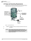
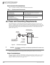
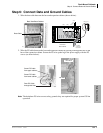
10. Ground the system according to “AC Power and Grounding Requirements” on page 3-4.
11. Go to “Step 16: Set Jumpers and Install Option PCBs onto the ACTU” on page 3-20.
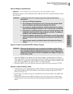
WARNING! To prevent electrical shock, make sure the power supply is not plugged into
the AC outlet.