


T1
RDTU3A Call Data Information
8-10 Strata CTX I&M 06/04
RDTU3A Call Data Information
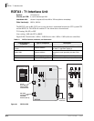
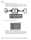
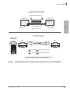
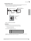
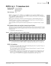
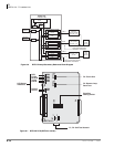
RDTU3A has an RS-232C port to trace data that the RDTU3A sends and receives from the CTX
system processor. The T1 line alarm data can also be monitored with the RDTU3.
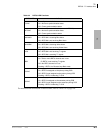
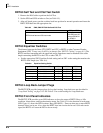
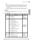
Commands
You can type the commands in the following table to check the status indicators also described in
the table below.
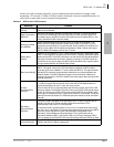
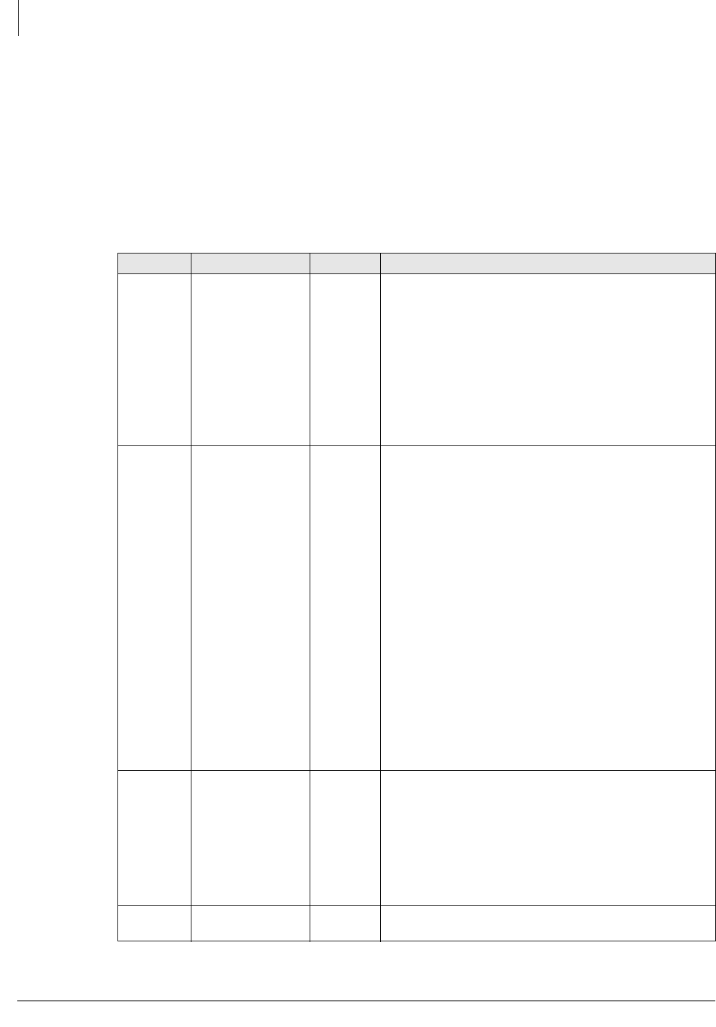
Table 8-7 RDTU3 Status Commands
Command Function Format Indication
U
When you power
On or when you
enter “U,” the unit
name and software
version appears.
u [RTN]
RDTU3A © TOSHIBA 2002 VER.1A
UNIT MODE:FFMxx SCHxx TSxx RPDxxxx TPDxxxx
ZCSxx
ERR:CRCyyy SLPyyy FSYyyyy BPVyyyyy
ALARM:YA on/off BA on/off FSL on/off
CRC = CRC Error in ESF mode
SLP = Slip error
FSY = Frame Sync error
BPV = Bipolar violation error
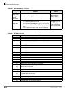
CH
Channel mode
check command
C v [RTN]
v = 0 to 23
Note: H = 1
or 0
CH.vv : DTxx DRyy DDTon/off
CH MODE: Ax
Explanation:
CH.vv:vv = channel numbers 0~23
DTxx:xx = DHin data code for RDTU3A to RCTU (see Tabl e
8-9)
DTyy:yy = DHout datacode RCTU to RDTU3A (see Table
8-10)
DDTon/off:
DDT1 = RDTU cannot receive requests from the central
processor at this time (see following Notes).
DDT0 = RDTU is available to receive requests from the
central processor
CH MODE:
A8 = CO loop, A0 = CP grpimd. AA = Tie immediate, AB =
Tie Wink, AC = DID Immediate, AD = DID WInk
This information is the same as “2-2 Data-HWY code” and
“2-5 Channel Trunk Type information.”
Loop back
Set RDTU3A into
the Remote Loop
Back mode
Useful for checking
remote equipment.
When RDTU3A is in
this mode, BSY
LED will flush.
L [RTN] L
Quit Loop
back
Quit Loop back
mode
Q [RTN] Q