


PCB Installation
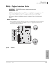
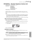
ASTU – Standard Telephone Interface Unit (CTX100 only)
Strata CTX I&M 06/04 6-5
PCB Installation
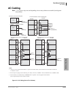
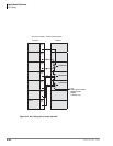
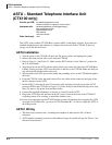
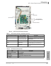
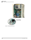
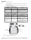
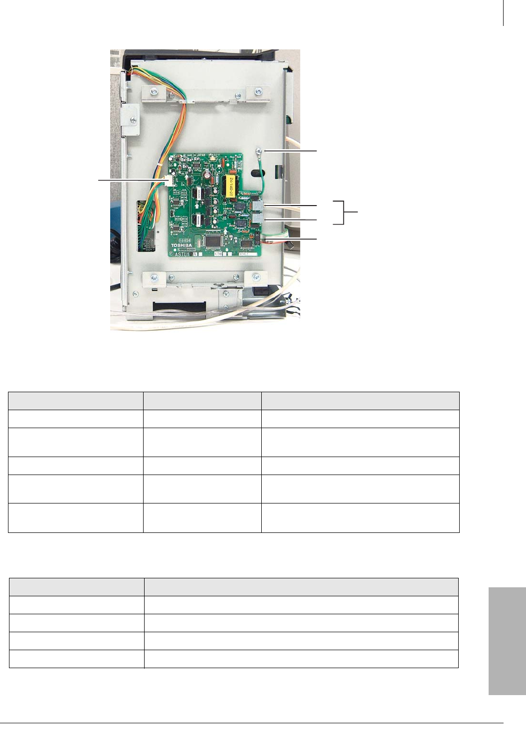
Figure 6-1 ASTU Controls and Interface Connectors
Table 6-1 ASTU Controls, Indicators, and Interface Connectors
Control/Indicator/Connector Type of Component Description
P1 5-wire connector cable Connects to the motherboard for supply power.
P2 10-wire connector cable
Connects to the processor PCB for data and
signal highway.
J1, J2 RJ11 - 6-pin modular Interfaces with single-line devices.
SW2 Jumper plug
Factory shipped in “Mu law” position. For
countries requiring “A Law,” switch to “A.”
FG1 Green Wire
Connects to the chassis with a screw (frame
ground).
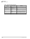
Table 6-2 ASTU Electrical Characteristics
Item Description
Single line device interface RJ11 Connector
Ringer Type Square Wave
Ringer Voltage 190Vp-p Open Voltage (Square Wave)
Line Voltage -24V
FG1
Frame Ground
P1
Power Connector
P2
Connects to ACTU P8
J2
J1
RJ11 Connections
for single-line devices
6634