MDF PCB Wiring
Station Wiring Diagrams
Strata CTX I&M 06/04 10-9
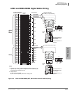
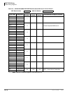
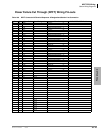
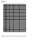
MDF PCB Wiring
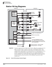
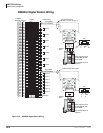
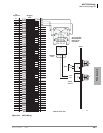
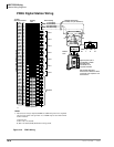
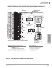
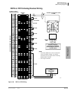
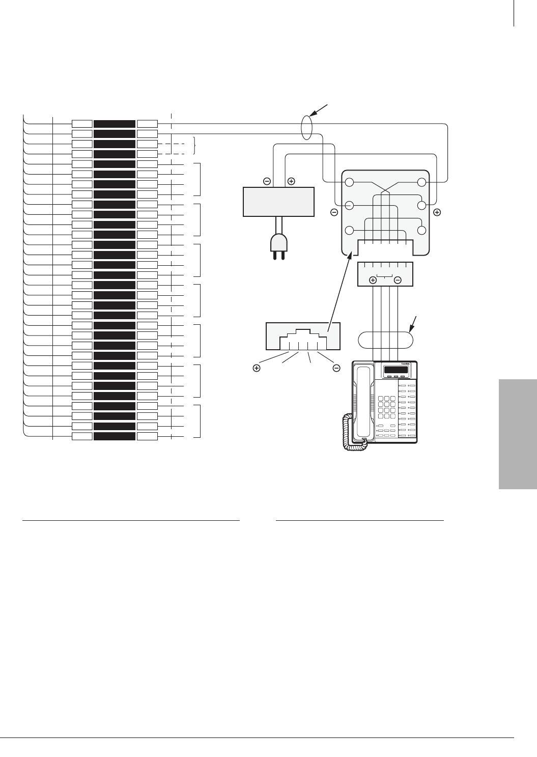
Digital Telephone DSS and DDCB External Power Connection
Figure 10-6 Digital Telephone DSS and DDCB External Power Connection
1
2
3
4
5
6
7
8
9
10
11
12
13
14
15
16
17
18
19
20
21
22
23
24
25
26
27
28
29
30
31
32
1
2
3
4
5
6
7
8
9
10
11
12
13
14
15
16
17
18
19
20
21
22
23
24
25
26
27
28
29
30
31
32
W-BL
BL-W
W-O
O-W
W-GN
GN-W
W-BR
BR-W
W-S
S-W
R-BL
BL-R
R-O
O-R
R-GN
GN-R
R-BR
BR-R
R-S
S-R
BK-BL
BL-BK
BK-O
O-BK
BK-GN
GN-BK
BK-BR
BR-BK
BK-S
S-BK
Y-BL
BL-Y
26
1
27
2
28
3
29
4
30
5
31
6
32
7
33
8
34
9
35
10
36
11
37
12
38
13
39
14
40
15
41
16
Bridging
Clips
BDKU or PDKU
Connector
25-PAIR CABLE W/MALE AMP CONNECTOR
CKT 2
(-) T1 (Voice/Data)
(GND) R1 (Voice/Data)
PT1
RT2
T2
R2
PT2
PR2
T3
R3
PT3
PR3
T4
R4
PT4
PR4
T5
R5
PT5
PR5
T6
R6
PT6
PR6
T8
R8
PT8
PR8
Jacketed Twisted Pairs
24AWG (1 Pair)
Station Cabling
GN
Y
BL
R
BK
W
R1
T1
(-)
T
GND
R
RJ11
Digital Telephone
(with or w/out BPCI-DI, ADM)
or...
DDSS, DDCB, BATI
(Not Used)
CKT 3
CKT 4
CKT 5
CKT 6
T7
R7
PT7
PR7
CKT 7
CKT 8
AC/DC External
Power Source
3245
654321
TR
To 120VAC Commercial
Power Outlet
AC/DC External Power Source Specifications:
PT/PR power wires are not available on the BDKS or BWDKU.
AC IN:
DC OUT:
120VAC ± 10%
24VDC ± 10%
160 MA (Min.) DC Current
200 MV P-P (Max) AC Ripple On DC Output
External Power Straps:
If the external power is installed, cut the
external power straps located inside the
digital telephone DDSS, DDCB.
DC Output
AC Input
2-Pair
Modular Cord
Required
5665
AC/DC power supplies that meet the above requirements are
available from most telephone equipment supply houses.
See Table 10-1 on page 10-2
for external power


