


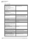
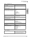

Strata CTX Configuration
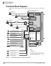
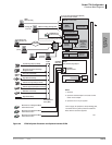
Functional Block Diagrams
2-20 Strata CTX I&M 06/04
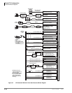
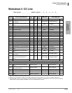
Figure 2-7 CTX100 and CTX670 CO Line Side Functional Block Diagram
RDTU2 or RDTU3?
• 2T1 / DS1(24 Channels / Lines)
• Loop Start, Ground Start, Tie, DID
Channel
Service
Unit (CSU)
25-pair Amphenol
TOSHIBA NDTU Cable
DB15
PLL Synchronization Circuits
2
RCOU3
4 Loop Start Co Lines (Analog)
RGLU2, RGLU3
4 Loop or Ground Start CO Lines (Analog)
RCOS
(Optional PCB on RCOU Only):
4 Loop Start CO Lines (Analog)
RCIU2
RCIS
4 Caller ID Circuits
4 Caller ID Circuits
(Two 4-Wire Modular Jacks)
MDF
(Two 4-Wire Modular Jacks)
(Two 4-Wire Modular Jacks)
(Two 4-Wire Modular Jacks)
(Two 4-Wire Modular Jacks)
1
RDDU
4 DID CO Lines (Analog)
REMU
4 E&M Tie Lines (Analog)
(REMU, Four 8-Wire Modular Jacks)
(Two 4-Wire Modular Jacks)
Secondary Protectors
2
BPTU1 or RPTU1 or 2
ISDN PRI (23B+1D channels)
Digital Voice/Data
Toshiba RPRI-CBL-KIT
Channel
Service
Unit (CSU)
8-wire Modular Jacks
2
ISDN BRI (U)
2 Circuits (NT-1?)
Voice/Data (2B+D)
RBUU
RBUS
ISDN BRI (U)
2 Circuits (NT-1)
Voice/Data (2B+D)
U
3
U
3
8-wire Modular Jacks
8-wire Modular Jacks
ISDN BRI (S/T)
2 Circuits (TE)
Voice/Data (2B+D)
RBSU
NT1 per circuit
2
U
3
T
3
8-wire Modular Jacks
RMCU
Trunk Circuits for E911
RCMS 2 Trunk Circuits
RCMS 2 Trunk Circuits
CAMA Line (2-wire Modular Jacks)
CAMA Line (2-wire Modular Jacks)
Network
Demarcation
Point
Remote Location(s)
Remote
Location(s)
BVPU
Voice Over IP Unit (4 Circuits)
BDKU/BDKS or PDKU
(CTX100 & CTX670) or
RRCU
Remote Cabinet Interface Card
Optical Fiber Cable
3 km/(1.86 mi.)
10Base-T
CTX Expansion
Cabinets
Digital
Telephone
MCK
EXTender
MCK
Gateway
IP Network
IP Network
6739
4
Central Office
Centrex
PBX
Common Carrier
Other Telephone System
E911 Public Safety Answer
Point (PSAP)
Priviate Networking Lines
•
•
•
•
•
•
•
•
•
•
•
•
Data and Speech Highway
QSIG networks (RPTU2)
4
PageScrollMode Feature
Msg
MicRedial
Spdial
Spkr
Cnf/Trn
Hold
Vol
PageScrollMode Feature
Msg
MicRedial
Spdial
Spkr
Cnf/Trn
Hold
Vol
1. RCIU2/RCIS tip/ring cross
connected to RCOU, RCOS, or
RGLU tip/ring at MDF.
2. Customer-supplied equipment.
3. U, S, T, R, are ISDN reference
model termination points.
4. RPTU2 is required for QSIG
Networking.
CTX / DK
BVPU
Remote
Node(s)
BIPU-Q2A
Strata Net QSIG Over IP Unit
100Base-TX
CTX
BIPU-Q1A
(CTX100 only)
ADKU
Remote Location(s)
BIPU-M2A
IP Telephone
With or without
VPN Router
or Server
With or without
VPN Router
or Server
IP Network
IP Network