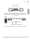
CTX28 Installation
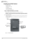
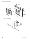
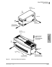
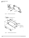
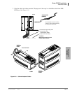
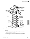
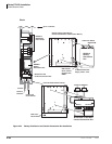
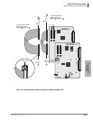
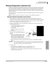
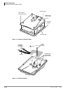
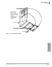
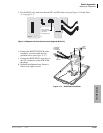
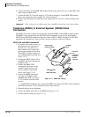
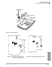
Installing the CTX28 Cabinet
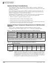
1-10 Strata CTX I&M 06/04
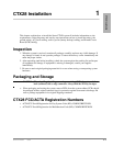
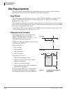
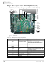
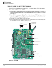
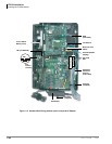
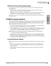
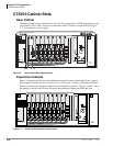
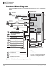
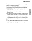
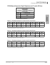
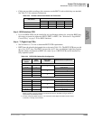
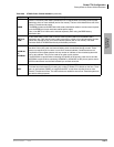
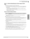
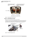
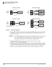
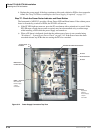
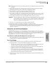
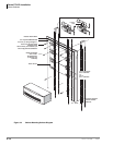
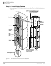
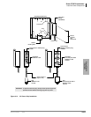
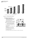
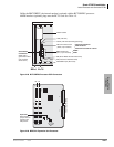
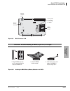
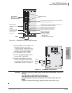
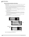
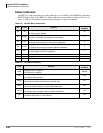
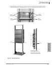
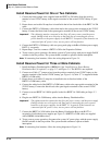
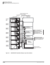
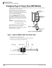
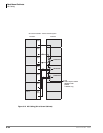
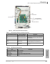
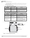
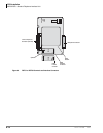
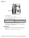
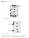
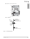
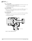
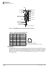
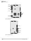
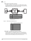
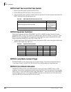
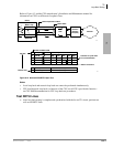
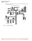
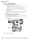
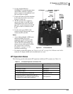
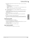
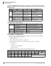
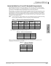
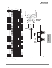
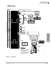
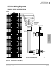
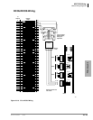
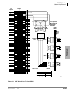
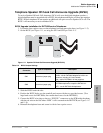
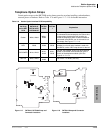
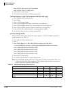
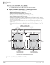
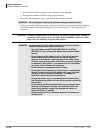
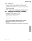
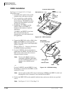
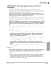
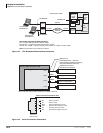
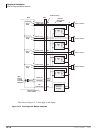
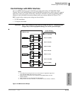
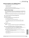
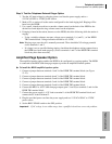
Step 1: Set Jumpers on the GMAU1A (Motherboard)
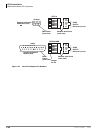
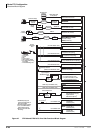
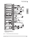
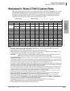
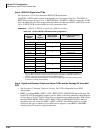
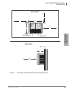
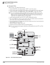
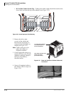
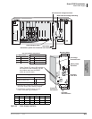
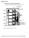
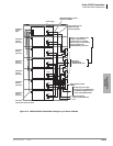
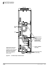
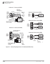
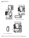
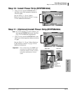
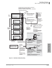
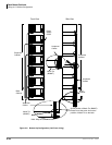
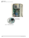
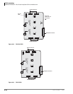
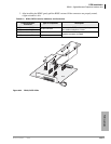
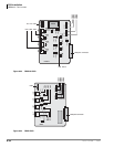
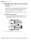
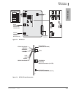
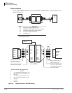
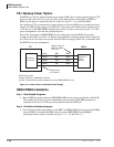
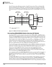
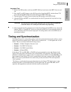
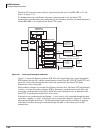
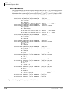
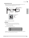
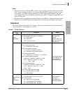
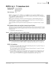
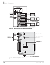
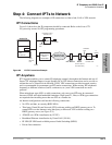
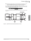
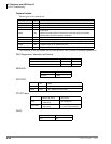
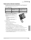
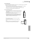
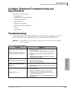
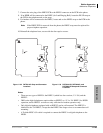
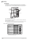
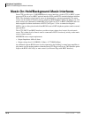
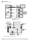
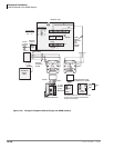
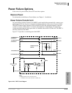
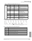
The GMAU1A (shown in Figure 1-7) supports up to 6 CO lines with Caller ID (CLID).
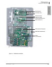
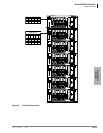
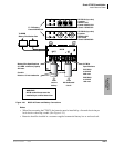
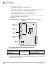
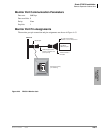
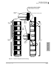
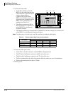
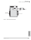
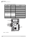
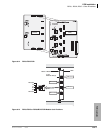
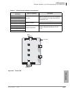
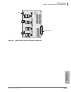
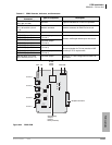
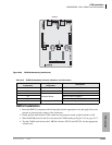
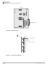
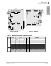
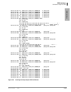
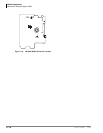
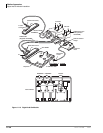
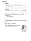
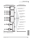
Figure 1-7 GMAU PCB
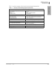
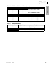
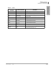
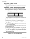
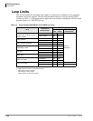
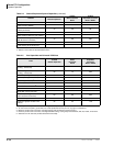
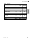
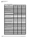
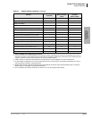
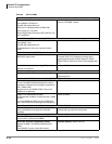
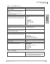
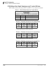
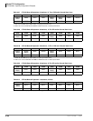
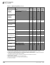
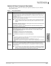
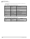
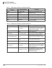
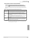
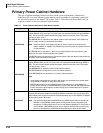
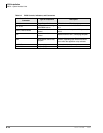
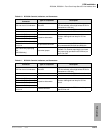
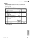
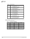
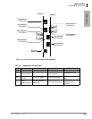
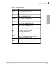
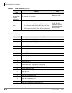
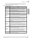
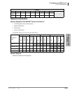
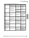
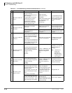
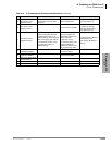
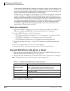
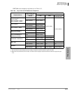
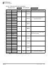
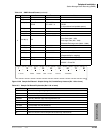
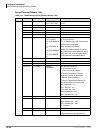
Table 1-4 GMAU Controls, Switches and Indicators
Control/Indicator/Connector Type of Component Description
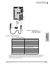
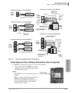
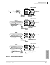
SW1 2-position slide switch
Power Switch:
[STANDBY] = no DC power supply.
[ON] = DC voltage supplied. [ON] activates the
reserve power from HPFB-6 battery pack.
SW400
2-position slide switch 3dB Pad switchSW500
SW600
CD6 LED
Power indicator; when SW1 is [ON], turned on.
Red both AC power and 3Reserve power. SW1
is [STANDBY], turned off.
TB1 Plate with screw Grounding for HPFB-6 external battery
TB2 Plate with screw Grounding for GETS Ethernet card
TB3 Plate with screw
Grounding for CTX28 system, connect to earth
ground
P1
50-pin Amphenol
connector
DKT, SLT and Power Failure Transfer interface
P3 44-pin DIN connector GMAS interface
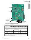
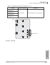
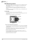
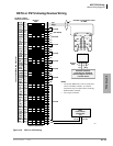
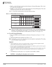
7113
SW1
ON/OFF
(Standby)
SW400
(3db/0DB)
SW500
(3db/0DB)
SW600
(3db/0DB)
CO1
TB2
P8
TB3
CO2
CO3
P6
P5
P7
P4
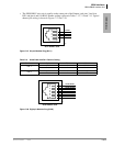
ON
STANDBY
SW1