


Station Apparatus
Digital Add-on Module Installation
Strata CTX I&M 06/04 11-21
Station Apparatus
Digital Add-on Module Installation
The DADM provides 20 buttons that can be flexibly programmed for any telephone feature that is
provided by the Strata CTX system. There are two DADM models available—DADM3020 and
DADM3120. The differences are shown in Table 11-8.
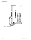
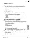
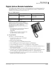
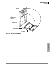
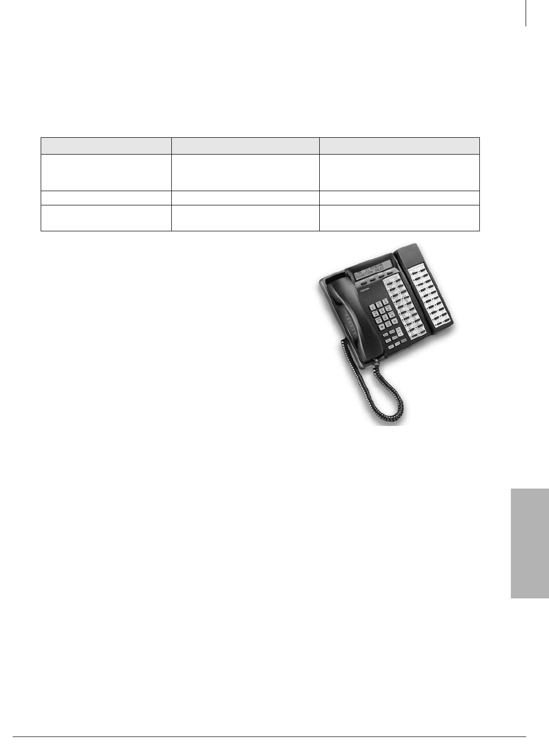
Install one or two DADM to a Toshiba digital
telephone (only) (shown at right) or an IP telephone.
The digital telephone and the DADM must belong to
the same series, i.e., 3000- or 2000-series.
IPT1020-SD telephones can only be connected to a
DADM3120.
• See the appropriate system Installation Chapter for
loop length and secondary protection
requirements.
• DADMs cannot be installed on telephones that
have BPCI, BVSU or DVSU installed.
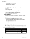
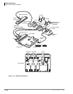
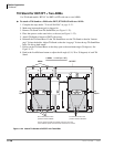
³ To install DADMs
See Figure 11-15 and follow these steps:
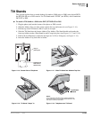
1. Loosen the four captive screws on the digital
telephone base and remove it.
2. Remove the base handset hanger.
3. Loosen two captive screws on DADM and remove bases.
4. Put the DADM supplied cable through the telephone and DADM bases.
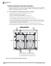
5. Connect DADM cable connectors to P1 of DADM and P1 of DKT telephone.
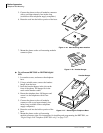
6. Install base of DADM and telephone – tuck DADM cable into DADM and telephone base, as
necessary, for proper length.
7. Secure DADM to telephone base with DADM connecting plate (using four screws).
8. If required to achieve maximum distance, install two-pair house cable (or external power) and
two-pair modular cord, supplied with DADM. (See Chapter 10 – MDF PCB Wiring.)
9. If a second DADM should be installed, connect P1 of the second DADM to P2 of the first
DADM with the DADM connecting cable.
Table 11-8 DADM Comparison
Add-on Module DADM3020
DADM3120
Telephone to be connected
DKT3010-S/20-S/10-SD/20-SD,
DKT3014-SDL
IPT1020-SD,
DKT3010-S/20-S/10-SD/20-SD,
DKT3014-SDL
Color of DADM Black, white Black
Power Source of ADM
Circuit
24 VDC 5 VDC
5843