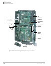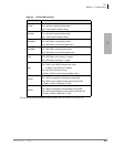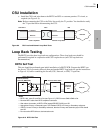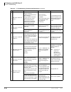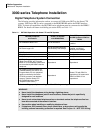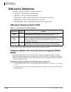
PCB Installation
RCIU1, RCIU2, RCIS – Caller ID Interface
6-20 Strata CTX I&M 06/04
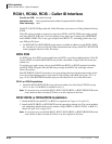
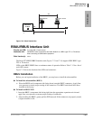
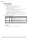
RCIU1, RCIU2, RCIS – Caller ID Interface
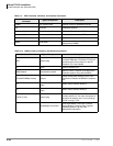
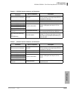
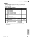
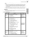
Circuits per PCB:
four Caller ID circuits
Interfaces with:
loop or ground start lines w/Caller ID (requires RCOU or RGLU2)
Older Version(s):
none
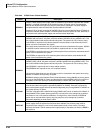
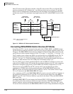
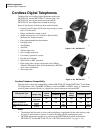
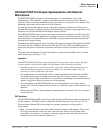
The RCIU1, RCIU2 PCB provides the Caller ID feature, also known as Calling Number Delivery
(CND).
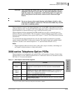
Caller ID can be provided on analog loop start lines (PCOU or RCOU PCBs) and analog ground
start lines (RGLU2 PCB) only. It is not available on any other type of analog lines (RDDU/DID
and/or REMU, PEMU Tie) or any type of digital lines (RDTU- T1, including ground start, loop
start, DID and Tie lines).
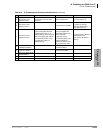
³ An RCIU1/RCIS or RCIU2/RCIS circuit must be available in addition to each RCOU, RGLU,
etc., line that is to receive Caller ID. When ordered from the factory, the RCIU1, RCIU2 PCB
comes equipped with four Caller ID circuits.
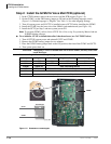
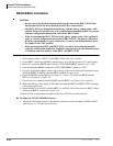
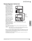
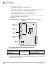
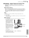
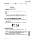
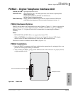
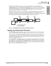
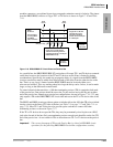
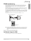
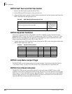
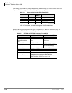
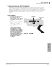
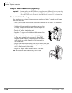
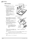
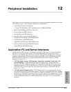
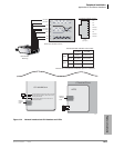
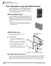
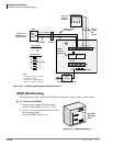
RCIS PCB
An RCIS piggy-back PCB can be installed onto the RCIU to provide an additional four Caller ID
circuits. Hence, an installed RCIU/RCIS can provide a maximum of eight Caller ID circuits per
cabinet slot.
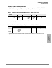
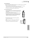
To provide up to eight circuits, always install RCIS onto RCIU1 or RCIU2 instead of installing
two RCIU PCBs (Program 100 code 009 always assigns each RCIU slot with eight software
Caller ID circuits).
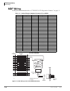
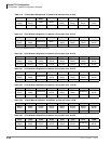
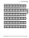
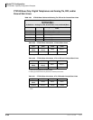
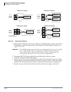
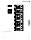
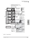
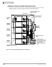
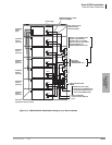
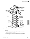
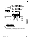
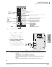
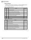
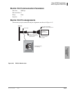
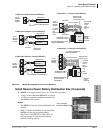
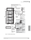
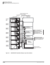
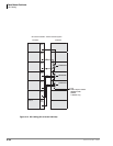
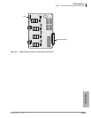
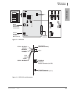
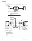
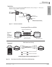
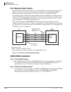
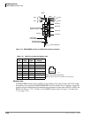
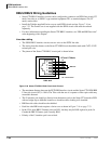
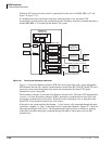
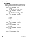
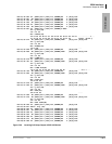
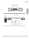
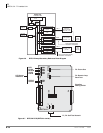
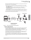
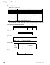
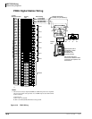
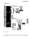
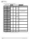
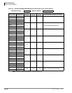
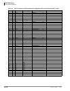
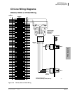
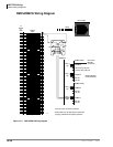
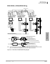
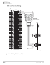
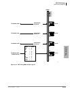
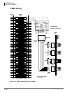
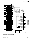
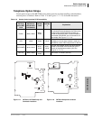
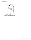
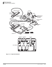
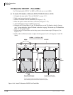
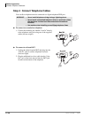
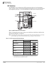
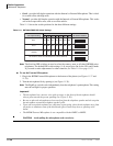
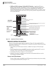
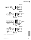
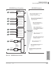
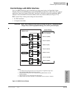
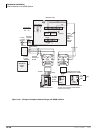
Each RCIU/RCIS Caller ID circuit has a two-wire tip/ring interface which must be bridge-wired
across its corresponding ground or loop start CO line tip/ring on the MDF (see Figure 10-11 on
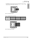
page 10-20). Each RCIU/RCIS modular jack provides interface for two Caller ID circuits.
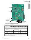
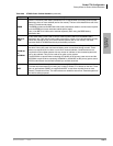
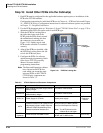
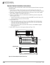
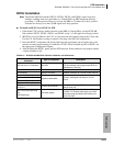
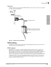
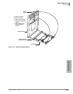
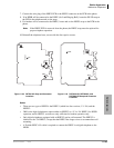
RCIU1 or RCIU2 Installation
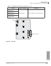
³ Install the RCIU1/RCIU2 PCBs in any universal cabinet slot of the Strata CTX670 (except
slot 11 or slot 12 if the RSIU is installed in slot 11).
Note It is not necessary to install the RCIU1, RCIU2, RCIU1/RCIS, or RCIU2/RCIS PCBs in the
same cabinet as their associated CO lines or in slots adjacent to the lines.
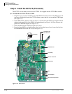
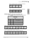
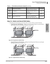
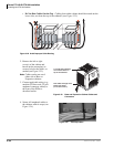
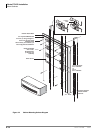
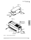
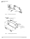
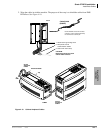
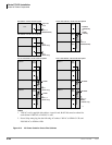
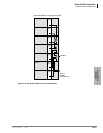
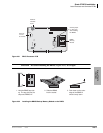
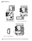
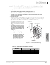
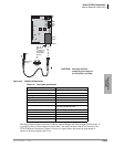
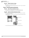
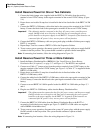
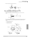
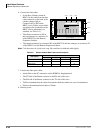
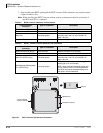
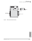
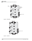
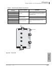
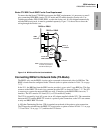
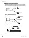
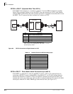
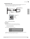
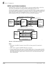
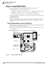
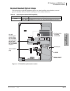
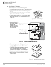
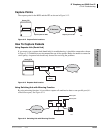
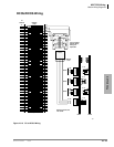
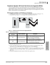
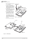
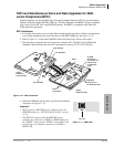
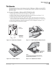
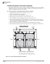
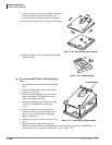
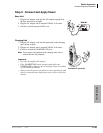
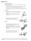
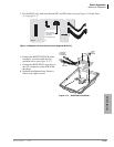
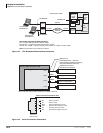
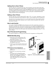
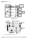
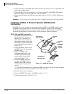
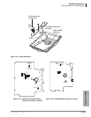
RCIU1/RCIS or RCIU2/RCIS Installation
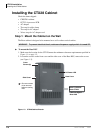
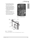
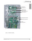
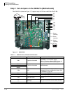
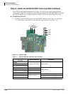
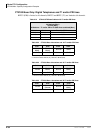
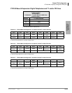
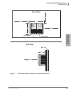
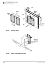
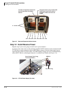
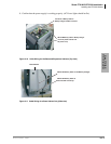
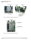
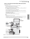
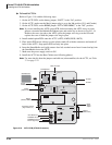
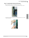
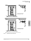
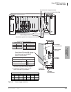
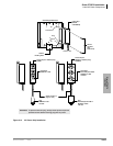
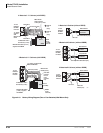
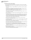
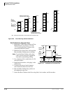
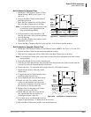
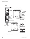
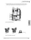
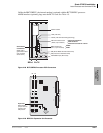
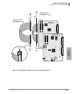
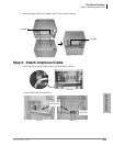
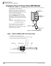
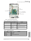
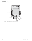
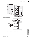
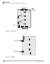
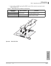
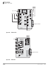
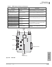
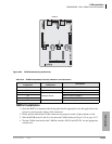
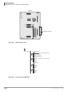
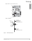
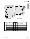
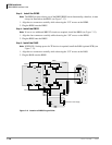
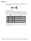
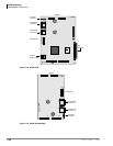
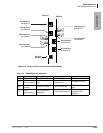
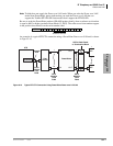
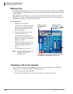
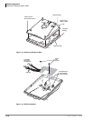
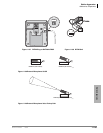
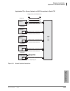
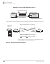
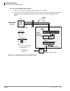
1. Install the RCIS onto the RCIU1 or RCIU2 as required (see Figures 6-14 and 6-15).
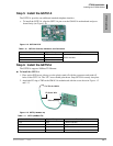
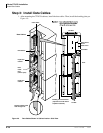
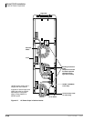
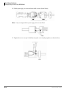
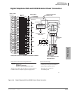
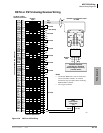
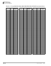
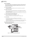
2. Install the RCIU1/RCIS or RCIU2/RCIS into the appropriate cabinet slot. The circuit modular
jack numbering and the tip/ring cross connect wiring of BECU to RCOU, PCOU, or RGLU is
shown in Figure 10-8 on page 10-13.
Note It is not necessary to install the RCIU1, RCIU2, RCIU1/RCIS, or RCIU2/RCIS PCBs in the
same cabinet as their associated CO lines or in slots adjacent to the lines.