


T1
RDTU Installation
8-6 Strata CTX I&M 06/04
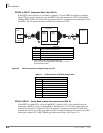
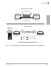
RDTU3 to PBX T1 (Separated More Than 655 ft.)
If the RDTU3 must interface to a customer’s premises T1 circuit (PBX, key/hybrid, or another
Strata CTX) to provide Tie line service, the RDTU3 must be connected to a CSU (with Toshiba
cable kit RDTU3-CBL-KIT) if the other customer premise T1 equipment is more than 655 ft. from
the RDTU. The T1 span on the other end must also connect to a CSU.
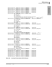
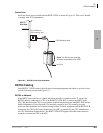
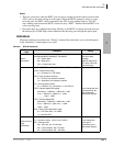
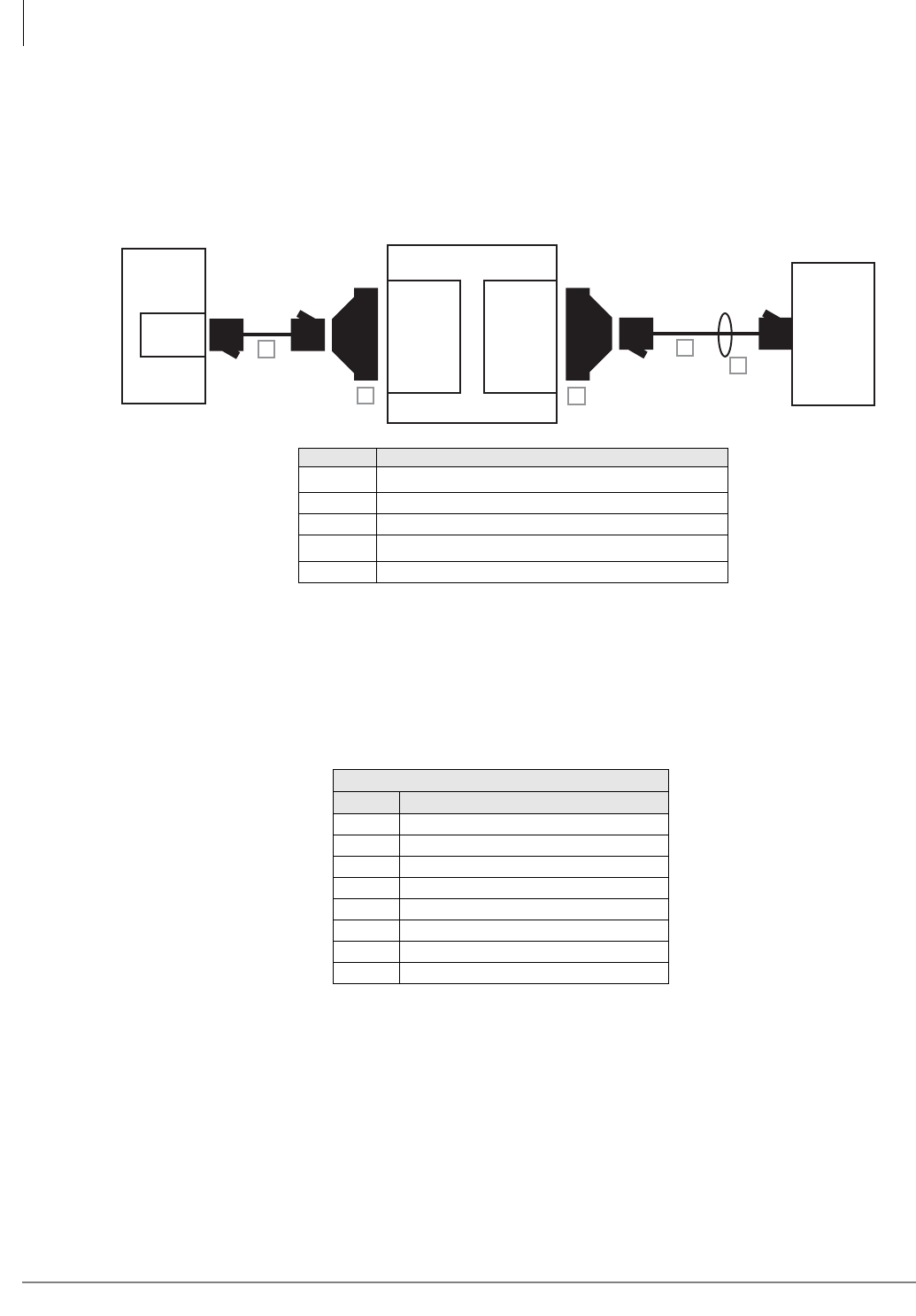
Figure 8-3 RDTU3 Connection to Digital Network or OCC
RDTU to PBX T1 - Direct Back-to-back Connection (up to 655 ft.)
If the RDTU is within 655 ft. of the far-end PBX T1 circuit, a CSU is not required. However,
connecting a RDTU T1 span to another PBX or Key/Hybrid T1, in a Tie line configuration at a
distance less than 655 ft. (without a CSU) will require a customer provided special cable. The
transmit and receive pair of this span cable must be crossed pairs and the wires must be 24 AWG,
twisted pair, otherwise 22 AWG, ABAM type cable must be used. (See Figure 8-4.)
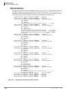
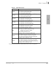
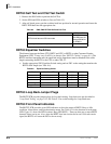
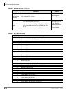
Table 8-4 Detailed Pinouts for RDTU3 Network Jack
Network Jack/RDTU3 Modular Jack
Pin Function
1 Tip – Receives from the network
2 Ring – Receives from the network
3 Not Used
4 Ring – Transmits to the network
5 Tip – Transmits to the network
6 Not Used
7 Not Used
8 Not Used
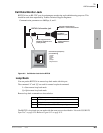
Network
Jack
or RDTU3
RDTU3
CSU (NIU)
DB15
(female)
DB15
(male)
6618
A
B
C
D
E
RJ45
Item Description
A
1
1. Items A and D come with the RDTU3-CBL-KIT.
Items A and D are straight-pinned data cables, not cross-
pinned telephony cables.
15 feet of CAT5 unshielded cable
B 1 DB15 modular adapter (CSU to network jack)
C 1 DB15 modular adapter (CSU to RPTU)
D
1
30 feet of CAT5 shielded cable
E 1 Ferrite core (supplied with RDTU3 PCB)