


PCB Installation
RDDU – Direct Inward Dialing Line Interface Unit
6-28 Strata CTX I&M 06/04
RDDU – Direct Inward Dialing Line Interface Unit
Circuits per PCB:
four DID lines
Interfaces with:
DID (one or two-way) lines
Older Version(s):
none
The RDDU provides four Direct Inward Dialing (DID) lines, each of which can have a single
office code along with a block of extensions.
Each extension can be assigned to ring a station [DN] that appears on one or multiple stations,
Distributed Hunt or ACD Group, or an external telephone number selected in system
programming. This enables calls over the same line to be routed to different stations or groups of
stations. An extension can also be assigned to ring the maintenance modem. Each RDDU can be
set for either wink start or immediate. All RDDU lines support DNIS and ANI features.
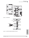
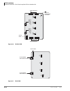
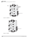
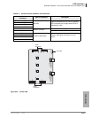
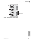
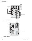
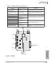
RDDU controls, indicators, and interface connectors are shown in Figure 6-21 and described in
Table 6-14.
RDDU Installation
Note Switches are factory-set to the 0 (0 dB signal level drop) position.
1. If the KSU is located within one mile of the PBX or CO, set dB Pad switches SW101 through
SW401 to the 3 (-3 dB signal level drop) position to control excessive loudness resulting from
close proximity to the PBX or CO.
2. Sensitivity jumpers P101~P401 are used mostly for dial pulse operation, to adjust for dial
pulsing at different loop lengths. If close to the central office, the sensitivity should be set for
low (L); as the loop length increases, it should be set to medium (M), then high (H).
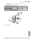
3. Insert the RDDU (component side facing right) into the appropriate slot and apply firm, even
pressure to ensure proper mating of connectors.
4. After installing the RDDU, gently pull the PCB outward. If the connectors are properly mated,
a slight resistance is felt.
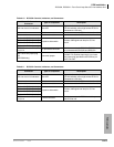
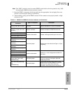
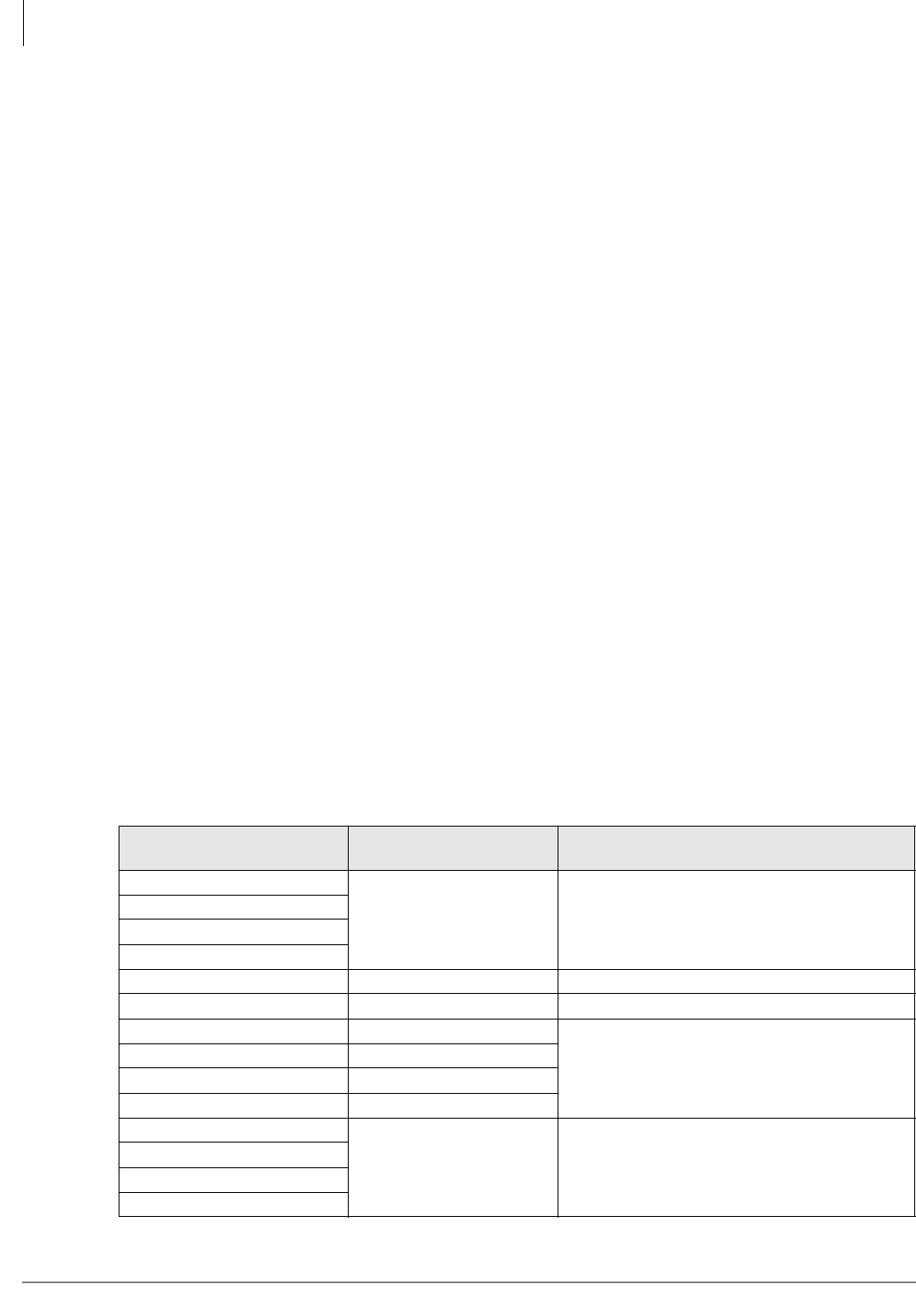
Table 6-14 RDDU Controls, Indicators, and Connectors
Control/Indicator/
Connector
Type of Component Description
Pad switch SW101 (circuit 1)
3-position slide switch Enables -3 dB signal level drop for line circuit.
Pad switch SW201 (circuit 2)
Pad switch SW301 (circuit 3)
Pad switch SW401 (circuit 4)
J1 connector Modular connection Interface connector for DID line circuits 1 & 2
J2 connector Modular connection Interface connector for DID line circuits 3 & 4
DID line circuit 1 CD122 Red LED (top)
Lights to indicate line circuit is in operation.
(Trunk indicator will not light unless RDDU is
connected to a DID line.)
DID line circuit 2 CD222 Red LED
DID line circuit 3 CD322 Red LED
DID line circuit 4 CD422 Red LED (bottom)
Jumper plug P101
3-terminal jumper plug Adjusts for dial pulsing at different loop lengths.
Jumper plug P201
Jumper plug P301
Jumper plug P401