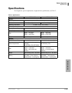
Strata CTX100-S/CTX100 Installation
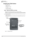
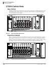
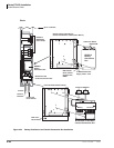
Installing the CTX100 Cabinet
3-20 Strata CTX I&M 06/04
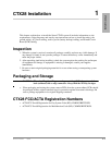
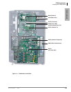
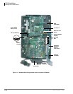
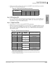
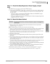
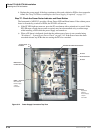
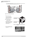
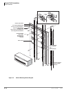
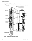
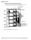
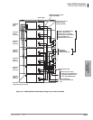
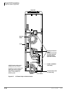
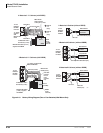
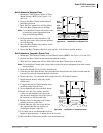
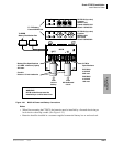
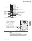
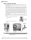
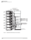
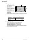
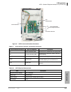
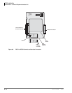
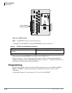
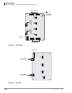
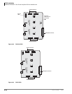
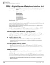
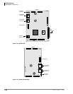
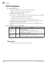
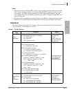
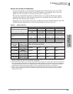
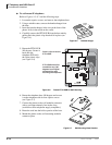
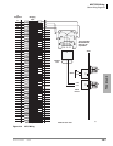
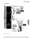
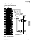
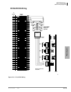
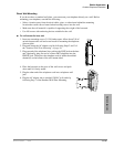
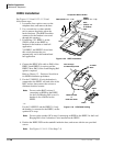
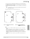
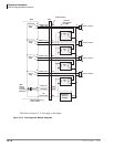
³ To Install ACTU1A
Refer to Figure 3-18 with the following steps.
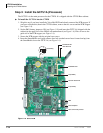
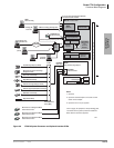
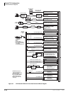
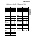
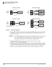
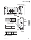
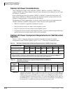
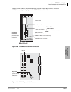
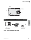
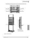
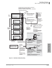
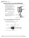
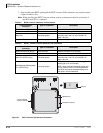
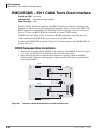
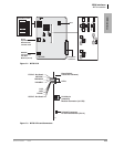
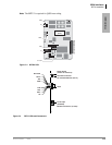
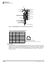
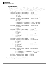
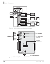
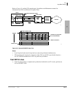
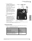
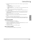
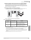
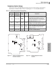
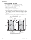
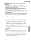
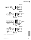
1. On the ACTU PCB, set the battery jumper, “BATT,” to the “On” position.
2. On the ACTU, make sure the Mu/A jumper plug is set to the Mu position (U.S. and Canada).
3. On the ACTU PCB, set the BBMS jumper “ATTACHED BBMS,” to the “NO” position.
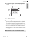
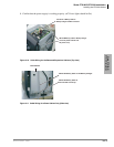
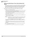
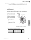
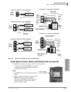
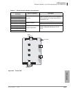
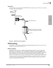
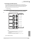
Note If you are installing the AETS option PCB, before mounting the AETS, dress its green
jumper wire under and behind the Ethernet port and out the top as shown in Figure 3-18.
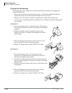
Remove the screw just above the AETS, place the jumper wire ring over the hole and
replace the screw to hold the jumper wire ring in place.
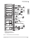
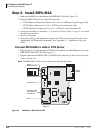
4. Install needed option PCBs onto the ACTU (AETS, AMDS, BSIS, ARCS).
5. Place option PCB arrow side up over the plastic stand-offs with the connectors and stand-off
holes on the ACTU. Snap option PCB securely into place.
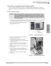
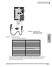
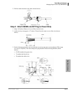
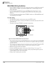
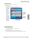
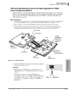
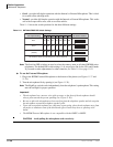
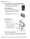
6. Insert the SmartMedia card (gold contacts face left, notched corner faces forward and up) into
the SmartMedia slot on the ACTU.
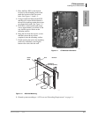
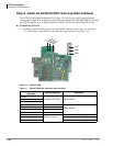
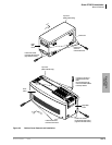
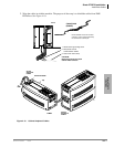
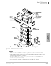
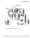
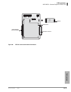
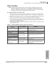
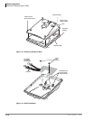
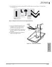
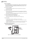
7. Make sure the power supply switch is Off.
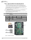
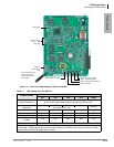
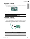
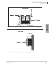
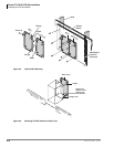
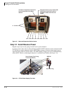
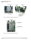
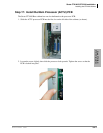
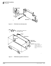
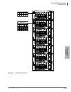
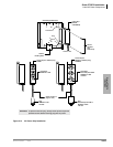
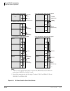
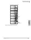
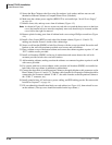
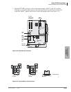
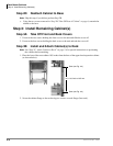
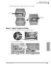
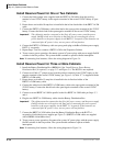
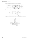
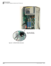
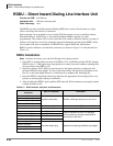
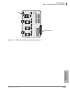
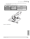
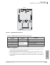
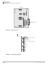
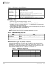
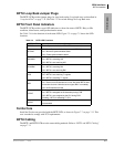
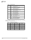
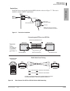
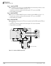
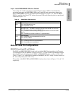
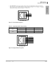
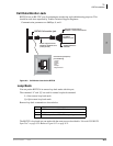
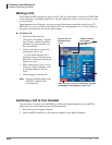
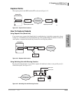
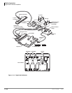
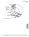
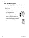
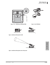
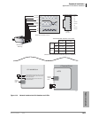
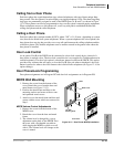
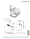
8. Install the ACTU into the Base Cabinet (see following photos).
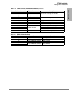
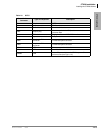
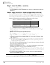
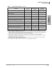
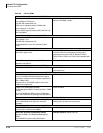
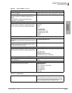
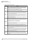
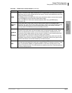
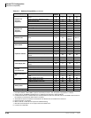
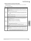
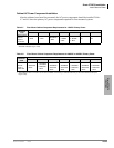
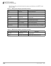
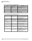
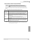
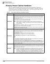
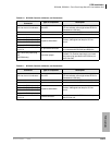
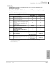
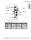
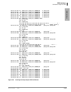
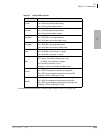
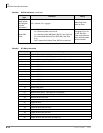
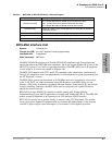
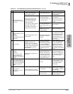
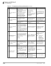
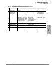
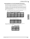
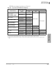
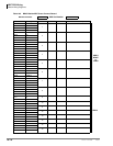
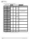
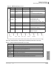
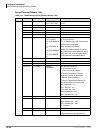
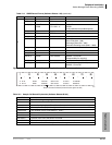
Note For more details about the jumpers and add-ons (subassemblies) for the ACTU, see Table
3-2 on page 3-22.
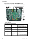
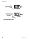
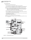
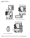
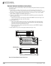
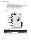
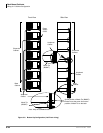
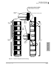
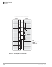
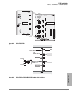
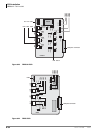
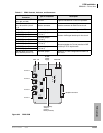
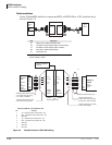
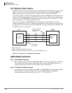
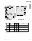
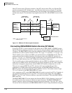
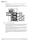
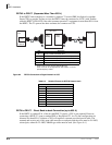
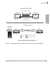
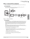
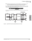
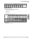
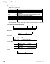
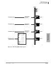
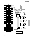
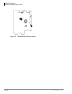
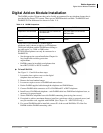
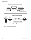
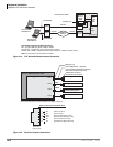
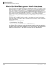
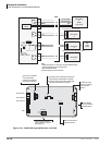
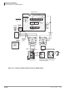
Figure 3-18 ACTU PCB (CTX100 Processor)
5897
600/600600/600 600/600
ON BACK UP
P101
Mu A
OFF
MOH1MOH2
UP
YES
P301
P302
ATTACHED
BBMS
P601
P801
NO
ACTU1A
AMDS1A
BSIS
ARCS1A
BSIS1A
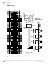
(RS232-C, SMDR and SMDI)
Control Relay Terminal
(Night Transfer, etc.)
MOH/BGM1 RCA Jack
600 ohm page output
Not Used
Not Used
UP UP
UP
AETS1A
Future MOH2 Jack
AETS1A
(10 Base-T Ethernet)
Ground
AETS Green Jumper Wire
Battery
Backup
Jumper
ARCS1A
(DTMF/ABR Circuits)
MOH/BGM Volume Control
SmartMedia Slot
SmartMedia Card
MU/A Law Jumper