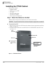
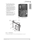
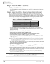
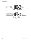
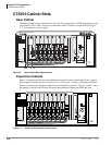
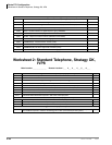
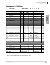
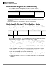
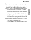
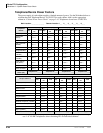
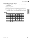
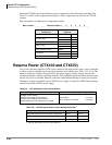
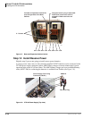
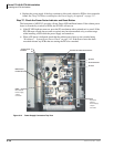
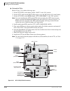
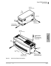
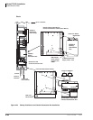
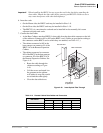
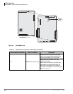
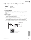
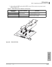
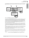
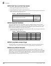
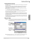
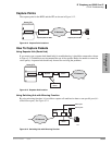
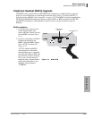
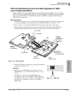
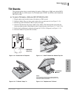
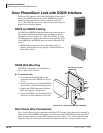
PCB Installation
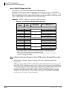
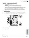
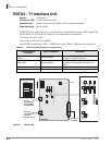
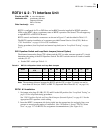
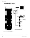
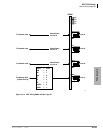
RGLU2 – Loop/Ground Start CO Line Interface Unit
6-36 Strata CTX I&M 06/04
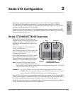
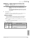
RGLU2 – Loop/Ground Start CO Line Interface
Unit
Circuits per PCB:
four line circuits
Interfaces with:
loop or ground start lines
Older Version(s):
RGLU1 (does not have hookflash to CO)
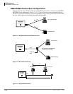
The RGLU2 also provides ring detection, dial outpulsing, and hold. Each RGLU2 line can be
programmed for DTMF or dial pulse signaling and gas tube secondary protection.
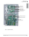
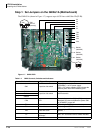
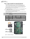
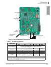
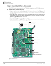
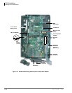
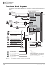
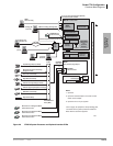
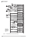
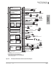
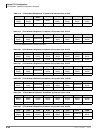
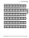
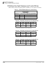
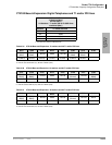
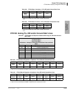
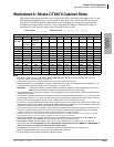
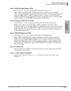
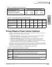
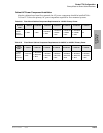
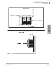
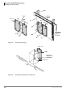
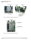
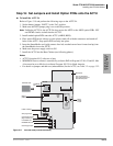
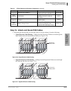
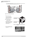
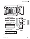
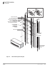
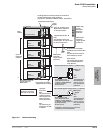
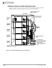
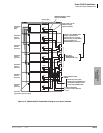
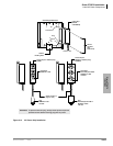
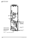
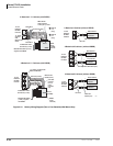
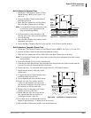
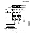
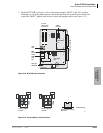
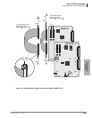
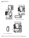
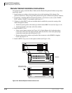
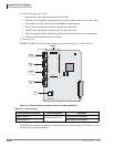
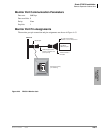
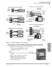
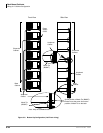
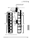
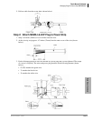
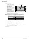
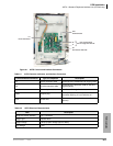
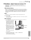
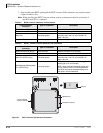
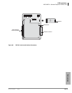
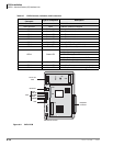
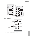
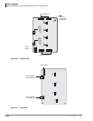
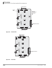
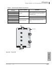
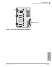
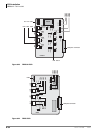
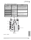
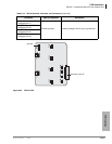
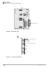
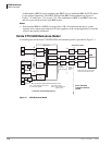
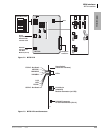
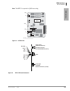
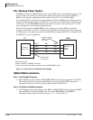
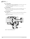
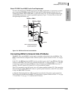
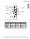
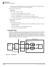
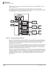
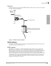
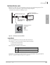
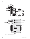
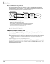
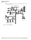
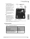
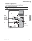
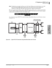
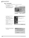
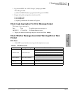
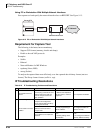
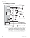
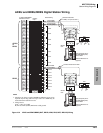
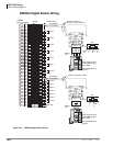
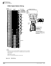
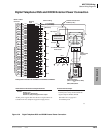
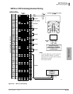
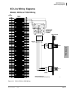
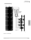
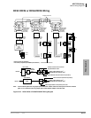
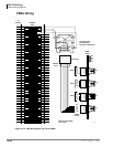
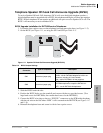
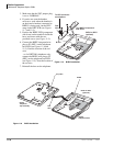
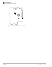
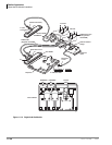
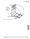
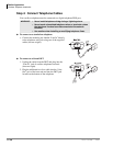
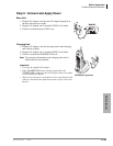
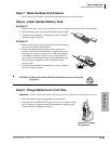
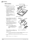
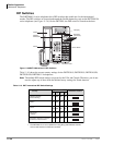
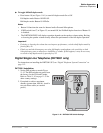
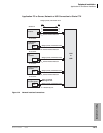
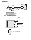
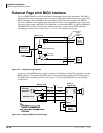
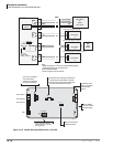
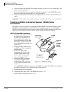
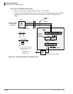
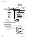
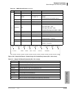
RGLU2 controls, indicators, and interface connectors are shown in Figure 6-26 and described in
Table 6-18.
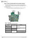
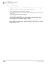
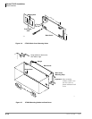
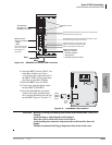
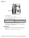
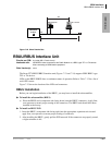
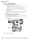
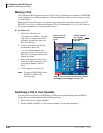
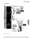
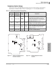
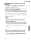
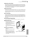
RGLU2 Installation
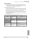
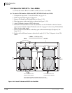
Note The decibel (dB) Pad switches SW101, SW201, SW301, and SW401 control excessive
loudness resulting from close proximity to a central office or PBX telephone office by
providing a -3 dB signal level drop to, or from, the PBX or central office when set to the 3
position. Switches are factory set to the 0 (0 dB signal level drop) position.
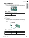
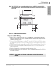
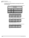
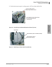
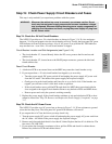
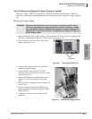
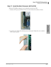
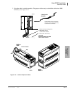
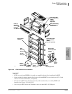
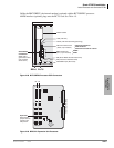
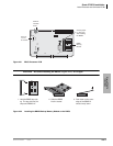
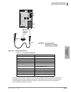
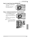
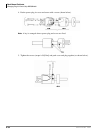
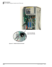
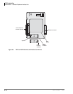
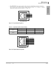
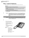
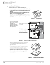
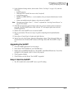
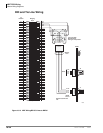
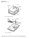
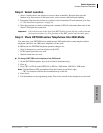
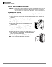
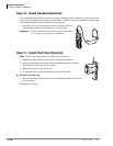
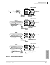
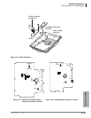
³ To install an RGLU2 PCB
1. If the Strata CTX670 is within one mile of the PBX or central office, set the dB Pad switches
SW101, SW201, SW301, and SW401 to the 3 (-3 dB signal level drop) position.
2. Set each line for ground start (GND) or loop start (LOOP) by setting the following jumper
plugs: SW103 for line 1, SW203 for line 2, SW303 for line 3, and SW403 for line 4.
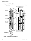
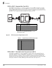
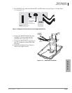
3. Insert the RGLU2 (component side facing right) into the appropriate slot and apply firm, even
pressure to ensure proper mating of connectors.
4. After installing the RGLU2, gently pull the PCB outward. If the connectors are properly mated,
a slight resistance is felt.
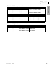
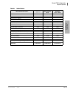
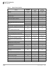
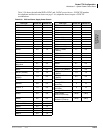
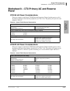
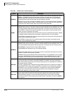
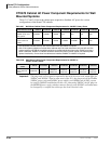
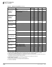
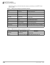
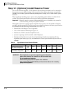
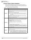
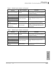
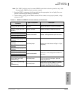
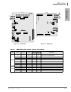
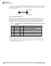
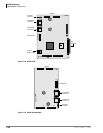
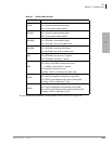
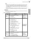
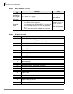
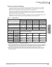
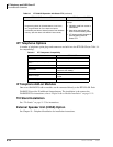
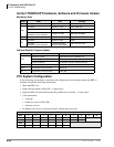
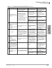
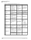
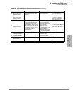
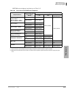
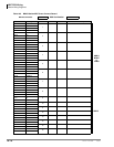
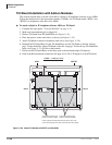
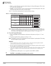
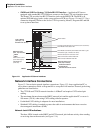
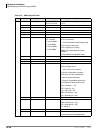
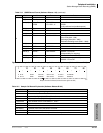
Table 6-18 RGLU2 Controls, Indicators, and Connectors
Control/Indicator/
Connector
Type of Component Description
Line circuit 1
Red LED
Lights to indicate that line circuit is in operation.
CO line indicator will not light unless RGLU2 is
connected to a line.
Line circuit 2
Line circuit 3
Line circuit 4
J1 connector Modular connector
RJ14 modular Interface connector for trunk
circuits 1 and 2.
J2 connector Modular connector
RJ14 modular Interface connector for trunk
circuits 3 and 4.
Pad switch SW101 (circuit 1)
2-position slice switch Enables -3dB signal level drop for trunk circuits.
Pad switch SW201 (circuit 2)
Pad switch SW301 (circuit 3)
Pad switch SW401 (circuit 4)