


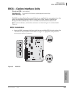
PCB Installation
BWDKU1A – Digital Telephone Interface Unit
Strata CTX I&M 06/04 6-17
PCB Installation
BWDKU1A – Digital Telephone Interface Unit
Circuits per PCB:
16 digital telephone circuits
Interfaces with:
all Toshiba digital telephones (corded and cordless, DDCB, DSS, ADM, BPCI)
CAUTION! Existing SpectraLink interface units are not compatible with the
BWDKU1A. A firmware update will be available from Spectralink in the
near future.
When installing Add-on modules, be sure to check Table 10-1 on page 10-2
to verify maximum line lengths. BWDKU supports 1 pair wiring per Table
10-2 on page 10-6.
Older Version(s):
none
The BWDKU1A is very similar to the BDKU + BDKS, but it supports 16 DKT circuits with a
single PCB. It is also compatible with Strata DK but only supports eight circuits.
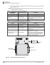
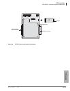
BWDKU1A Installation
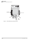
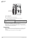
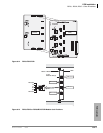
1. See Table 6-8 and Figure 6-12, then make any jumper adjustments needed for DKT or slot
requirements. The BWDKU1A can be installed in any slot; however, if it is installed in
expansion slots S_07~S_10, you must move the jumper plug to the “8 CCT” position.
Important! Do not detach the SWDR1A subassembly. The BWDKU1A will not work properly
without it.
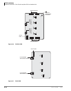
2. Insert the BWDKU1A (component side facing right) into the appropriate slot, and apply firm,
even pressure to ensure proper mating of connectors.
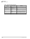
Table 6-8 BWDKU1A Slot Placement
Slot Numbers
Available
Circuits
BWDKU1A Jumper Settings
Base & Expansion
S_0 ~S_06
16
The CTX identifies the BWDKU1A as a BDKU + BDKS. Leave jumper plug
503 in the “BDKU” position and leave P504 in the “16 CCT” position.
Expansion
S_07~S_10
8
Move jumper 504 to the “8 CCT” position when the BWDKU1A is placed in
slots S_07~S_10. The BWDKU1A will work like a BDKU on a CTX system.
Note If the BWDKU1A is installed on DK system, move jumper P503 to
the “PDKU” position.