


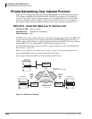

IP Telephony and QSIG Over IP
Private Networking Over Internet Protocol
9-42 Strata CTX I&M 06/04
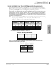
So the amount of bandwidth that is required on a segment to support a specific number of calls
is the sum of the number of channels multiplied by the bandwidth for the selected CODEC and
interval, plus the bandwidth required for the selected number of busy hour call attempts. And
the jitter is determined by the bandwidth of the WAN segment.
Example: If you want to support 4 calls using the G..711 CODEC with a 20 msec. interval, this
requires 4 x 88 kbps = 352 kbps of bandwidth. In addition, to support 1000 busy hour call
attempts, 6 kbps must be added for a total of 358 kbps. If only voice is going to be carried on
the segment, then a 384 kbps segment (6 B-channels) is sufficient. If voice and data are going
to be mixed on the segment, then at least 25% (89.5 kbps) should be added, or more, based on
the amount of data traffic desired. In this case, a total of 447 kbps will be required which
would best be supported by a 512 kbps segment (8 B-channels). This would result in an
expected jitter of 20 ms in the voice traffic.
BIPU-Q1A Installation
1. Make sure the BIPS1A daughter card is securely installed onto the BIPU-Q1A PCB (the
BIPS1A is installed on the BIPU-Q1A at the factory). See Figure 9-2 on page 9-6.
2. Install the BIPU-Q1A into one of the following slots:
• CTX100 Base and Expansion Cabinet slots (1~8, 16 channels per slot per Program 100)
• CTX670 Base Cabinet slots (1~8, 16 channels per slot per Program 100)
• CTX670 Expansion Cabinet slots (1~6, 16 channels per slot per Program 100)
3. Follow the procedure in Chapter 2 – Strata CTX Configuration to check the cabinet power
factor.
4. Power up the system. Refer to Table 9-2 for status indicators.
5. Program the CTX per the instructions in the Strata CTX Programming Manual.
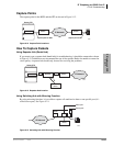
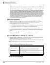
Connect BIPU-Q1A to LAN, Server or Router
1. Plug one end of a straight-through CAT5/5e/6 LAN cable into the RJ45 Ethernet port on the
BIPU-Q1A PCB in the CTX. (See Figure 9-2 on page 9-6.)
2. Plug the other end of the BIPU-Q1A CAT5/5e/6 LAN cord into a LAN, server or router jack.
Note The BIPU-M2A or Q1A-switch cables are straight-through cables.
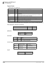
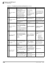
Figure 9-17 BIPU-Q1A or BIPU-M2A PCB
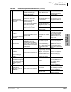
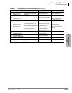
Table 9-14 BIPU-Q1A or BIPU-M2A Buttons, LEDs and Jumpers
Indicator Definition
Ethernet Port LEDs
RD - Indicates BIPU-M2A or BIPUQ1A receives data from switch.
LINK - Indicates data activity between BIPU-M2A and switch
SD - Indicates BIPU-M2A or BIPUQ1A sends data to switch.
Heartbeat LEDs
Flashes at a steady rate to indicate BIPU-M1A or BIPU-M2A or BIPUQ1A
is operating normally.
Status/Alarm LEDs For Toshiba Field Support Engineering use only.
Reset button Use when requested by Toshiba Field Support Engineer.
RS232 Maintenance Jack For Toshiba Field Support Engineers only.