


Strata CTX I&M 06/04 6-1
PCB Installation
PCB Installation 6
This chapter contains information on Printed Circuit Boards (PCBs) which can be used in the
cabinet slots of the Strata CTX systems.
Note Prior to PCB installation, the power supply must be tested and the ground checked.
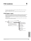
PCB Chapter Layout
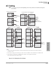
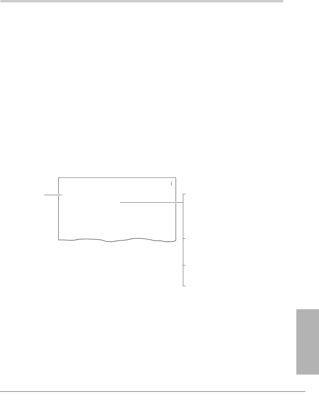
Each PCB outline begins with the PCB’s designation and title (the outline appears in the chapter in
alphabetical order by designation). A brief synopsis of the PCB appears next and includes a
notation of the system(s) that the PCB can be used in, the circuits supplied by the PCB, what
equipment the PCB interfaces with, and a list of the PCB’s older version(s) with a brief description
of their differences.
Installation instructions follow the synopsis with a table showing the PCB’s controls, indicators
and connectors and an illustration of the board.
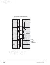
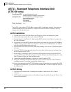
Systems: Strata CTX100
Circuits per PCB: four DID lines
Interfaces with: DID (one or two-way) lines
Older Versions: none
RDDU - Direct Inward Dialing Line Interface Unit
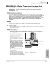
PCB Title
System:
Circuits per PCB:
Gives the type of system that is
compatible with the given PCB. Be
sure to read this information before
attempting to use a PCB with your
system application.
Type and number of circuits
available on the PCB.
Type of line/hardware the PCB can
accept.
Interfaces with:
Describes older version or versions
of the PCB.
Older Version(s):
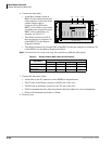
The RDDU provides four Direct Inward Dialing (DID) lines, each of which can have a single
office code along with a block of extensions.
Each extension can be assigned to ring a station [DN] that appears on one or multiple stations,
Distributed Hunt or ACD Group, or an external telephone number selected in system
programming. This enables calls over the same line to be routed to different stations or groups
of stations. An extension can also be assigned to ring the maintenance modem. Each RDDU
can be set for either wink start or immediate. All RDDU lines support DNIS and ANI features.
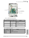
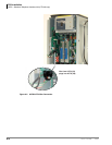
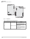
RDDU controls, indicators, and interface connectors are shown in Figure 4-17 and described
in Table 4-9.
PCB Installation
RDDU - Direct Inward Dialing Line Interface Unit
6040