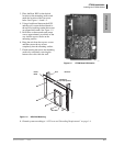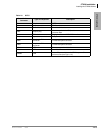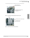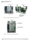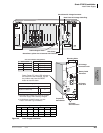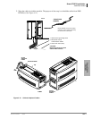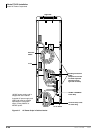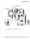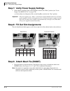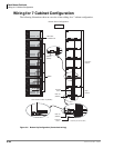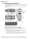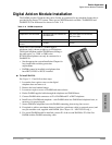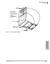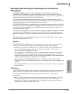
Rack Mount Cabinets
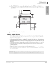
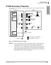
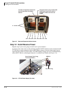
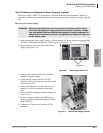
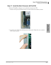
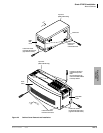
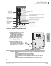
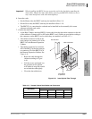
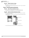
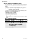
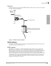
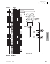
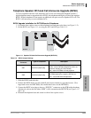
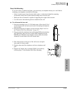
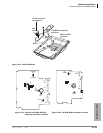
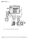
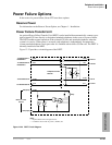
Step 12: (Optional) Install Reserve Power
5-16 Strata CTX I&M 06/04
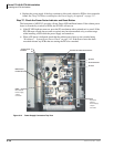
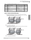
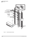
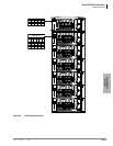
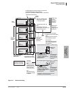
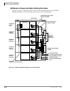
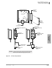
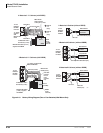
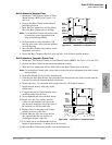
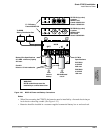
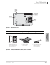
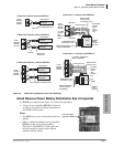
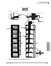
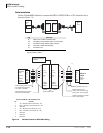
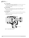
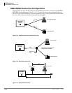
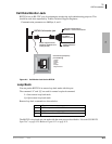
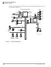
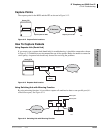
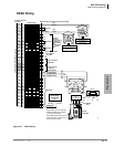
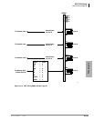
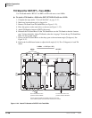
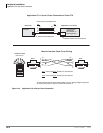
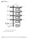
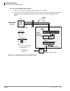
Install Reserve Power for One or Two Cabinets
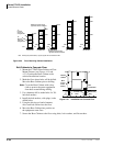
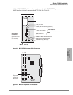
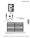
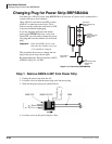
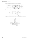
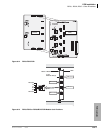
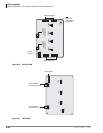
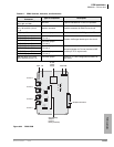
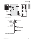
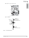
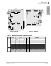
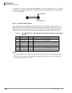
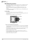
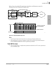
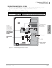
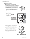
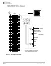
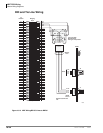
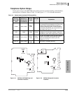
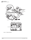
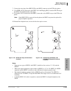
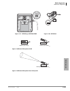
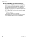
1. Connect the black jumper wire (supplied with the PBTC1A-3M cable) from the positive
terminal of one 12VDC battery to the negative terminal of the second 12VDC battery (Figure
5-4).
2. Ensure that a serviceable 10-amp fuse is installed in the in-line fuse holder of the PBTC1A-3M
cable.
3. Connect the PBTC1A-3M battery cable white lead to the open positive terminal of the 12VDC
battery. Connect the black lead to the open negative terminal of the second 12VDC battery.
Important! The cabinet(s) must be connected to the (live) AC power source, and the power
supply On/Off switch set to On prior to the final step of connecting the reserve
power batteries to the power supply via the BATT+/- receptacle. If the batteries are
connected after AC power is lost, reserve power will not function.
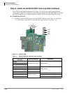
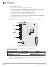
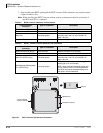
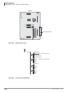
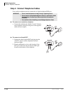
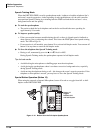
4. Connect the PBTC1A-3M battery cable two-prong male plug to the Base Cabinet power supply
BATT +/- receptacle.
5. Repeat Steps 3 and 4 to connect a PBTC1A-3M to the Expansion Cabinet.
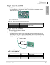
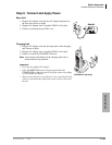
6. To test reserve power operation, disconnect system AC power plugs with power supply On/Off
switches in the On position. The system should continue to operate without interruption.
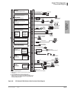
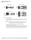
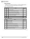
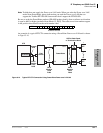
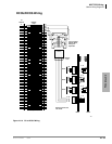
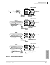
Note If connecting four batteries, follow the wiring diagram in Figure 5-4.
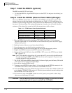
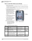
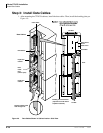
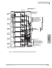
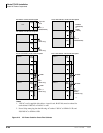
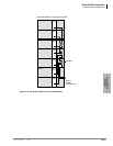
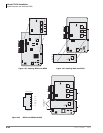
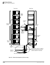
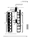
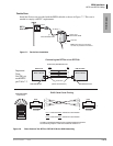
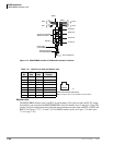
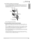
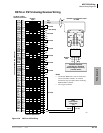
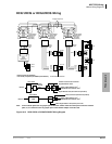
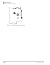
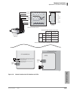
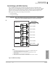
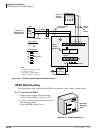
Install Reserve Power for Three or More Cabinets
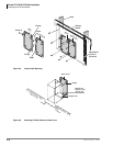
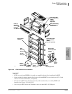
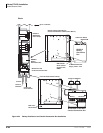
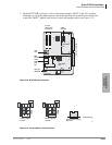
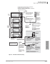
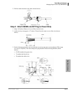
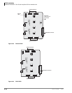
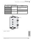
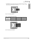
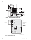
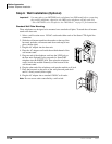
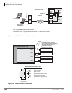
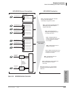
1. Install the Battery Distribution Box (BBDB1A). See “Install Reserve Power Battery
Distribution Box (if required)” on page 5-17 and Figure 5-4. The BCCB is not required.
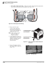
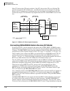
2. Connect two Cable “C” jumper wires from the positive terminal of one 12VDC battery to the
negative terminal of the second 12VDC battery, per Figure 5-4 (Cable “C” is supplied with the
BBTC1A-2.0M cable).
3. Ensure that a serviceable 15-amp fuse is installed in the in-line fuse holder of the
BBTC1A-2.0M battery cable.
4. Connect the white lead of the BBTC1A-2.0M battery cable to the open positive terminal of the
12VDC battery. Connect the black lead to the open negative terminal of the second 12VDC
battery.
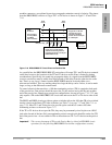
5. Connect a second BBTC1A-2.0M in parallel to the first BBTC1A-2.0M cable per Steps 2, 3
and 4.
6. Plug the two BBTC1A-2.0M battery cables into the Battery Distribution Box.
Important! The cabinets must be connected to the (live) AC power source, and the power supply
On/Off switches set to On prior to the final step of connecting the reserve power
batteries to the power supplies via the BATT +/- receptacle. If the batteries are
connected after AC power is lost, reserve power will not function.
7. Connect the BBTC2A-2.0M cables from the Battery Distribution Box to the BATT +/-
receptacle of individual power supplies per Figure 5-4 (BBTC2A-2.0M cables are supplied
with a BBDB1A distribution box).
8. To test reserve power operation, disconnect the system AC power plugs with the power supply
On/Off switches in the On position. The system should continue to operate without
interruption.
Note If connecting four batteries, follow the wiring diagrams in Figure 5-4.