


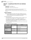

ISDN Interfaces
BRI U Overview
7-2 Strata CTX I&M 06/04
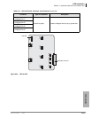
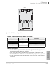
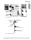
A subassembly (RBUS) can be attached to the RBUU for two additional BRIs for PSTN and/or
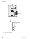
U-type station connections. The RBUU PCB and the RBUS subassemblies are shown in
Figures 7-23 and Figure 7-24 on page 7-28. The combination of RBUU and RBUS uses only
one slot to provide up to four U-type BRI circuits.
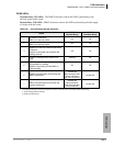
Notes
● Each installed RBUU or RBUS circuit provides a 2B + D connection and uses a system
capacity of two station ports and two CO lines regardless of the circuit application, even if the
circuit is not actually connected.
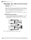
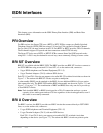
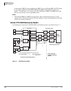
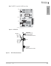
Strata CTX ISDN Reference Model
A block diagram of the Strata CTX ISDN PCBs and reference points is provided in Figure 7-1.
Figure 7-1 ISDN Reference Model
CTX (NT2)
R
S
U
T
U
ISDN
SWITCH
Demarcation Point
R
SLT
DKT
TE-1-S
(Voice or Data)
SLT
TA-S
TE-1-U
(Voice or Data)
RSTU
PDKU
RBSU/RBSS
(NTs
(P-MP)
RBUU/RBUS
RBSU
BPTU or
RPTU (TE)
RBUU/RBUS
(LT)
(P-P)
NT1
CSU
(NT1)
RJ48C
8-wire
RJ48C
8-wire
RJ48C
8-wire
Loop
Termination
Loop
Termination
Office
Channel
Unit
BRI
BRI
PRI
Office Channel Unit, or OCR, is
the CO Channel Service Unit
Dealer-
supplied
CSU and NT1
Telco-
supplied
Jacks
R, T, S, and U are ISDN standard reference points
Customer Premises Equipment
Public Switched
Telephone Network
(PSTN)
6643
PC
R
SLT TA-U
PC
P-P = Point-to-Point
P-MP = Point-to Multipoint
(passive bus)
TE-1 = Terminal Equipment, Type 1
TA = Terminal Adapter