


ISDN Interfaces
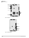
RBSU/RBSS Interface Units
Strata CTX I&M 06/04 7-23
ISDN Interfaces
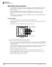
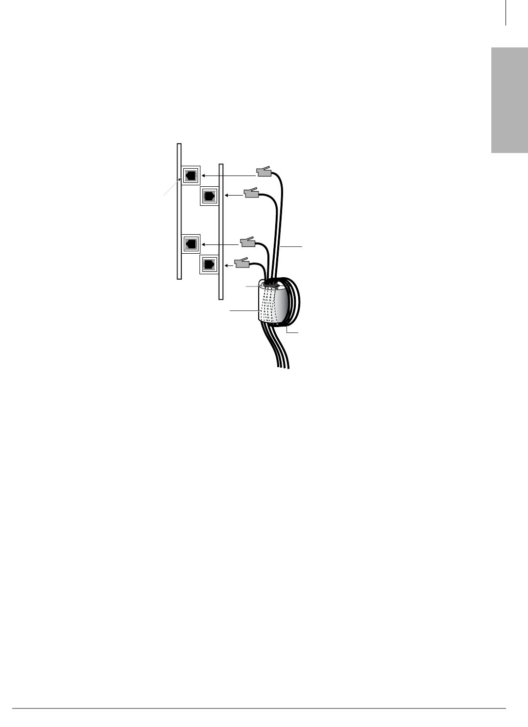
Strata CTX BRI Circuit EMC Ferrite Core Requirement
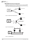
To ensure that the Strata CTX BRI circuit meets the EMC requirements, it is necessary to run all
wire connecting ISDN BRI circuits (TE, LT mode and NT mode) through a Ferrite core. Use
Toshiba part number, FER-CORE-ISDN, to order the ferrite core. It is not shipped automatically
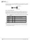
with the BRI circuit cards, it must be grounded separately. Figure 7-16 shows how to dress the
wiring through the Ferrite core.
Figure 7-16 BRI Circuit Ferrite Core Installation
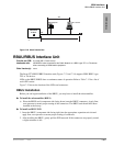
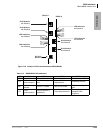
Connecting RBSU to Network Side (TE-Mode)
The RBSU only, not the RBSS, circuits can be connected to the network side of a BRI line. The
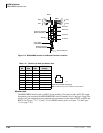
RBSU circuits must be configured in the TE-mode (refer to option switches in Table 7-8 on page
7-17).
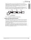
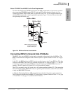
In the U.S., the BRI line from the ISDN service provider is a two-wire U-type BRI line. This line
connects to the RBSU TE circuit via a customer-provided NT1 as shown in Figure 7-17. The NT1
is necessary to convert the network BRI, two-wire, U interface to the RBSU BRI, four-wire, T
interface. The NT1 must be UL listed (U.S.) or CSA certified (Canada).
The NT1 is powered by local AC power via an AC adapter supplied with the NT1. The connection
between the NT1 and the RBSU TE circuit is a point-to-point connection, so the NT1 can connect
to only one RBSU BRI TE circuit.
A 100-ohm Terminating Resistor (TR) is required on each end of the point-to-point connection.
The TR must be switched into the RBSU TE circuit (refer to option switches in Table 7-11 on page
7-22 and Table 7-8 on page 7-17) and into the NT1 device.
RBSU or RBUU
4697
Ferrite Core
FER-CORE-ISDN
One Turn
CAT 3, 4,
or 5 Cable
Tie
Wrap
Note:
RBSS or RBUS
Locate the Ferrite core
as close as possible to
the BRI modular jack.
ISDN
PRI Jack