Strata CTX I&M 06/04 3-1
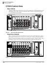
Strata CTX100-S/
CTX100 Installation
Strata CTX100-S/CTX100 Installation 3
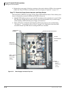
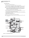
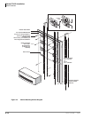
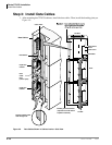
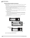
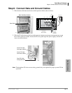
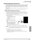
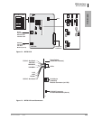
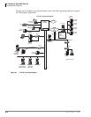
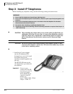
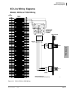
This chapter explains how to install the Strata CTX100-S/CTX100 systems. It includes
information on site requirements, wiring diagrams, and step-by-step instructions on how to install
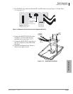
the unit(s), the ground wiring, AC power cabling, reserve power (battery backup) cabling, and
PCB cabling.
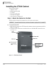
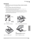
Inspection
1. When the system is received, examine all packages carefully and note any visible damage. If
any damage is found, do not open the packages. Contact the delivery carrier immediately and
make the proper claims.
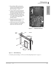
2. After unpacking (and before installing), check the system against the packing list and inspect
all equipment for damage. If equipment is missing or damaged, contact your supplier
immediately.
3. Be sure to retain original packaging materials for re-use when storing or transporting system
hardware.
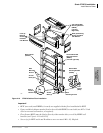
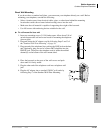
Packaging and Storage
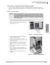
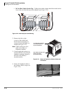
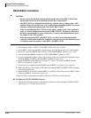
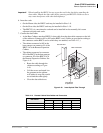
CAUTION! When handling (installing, removing, examining) PCBs, do not touch the
back (soldered) side or edge connector. Always hold the PCB by its edges.
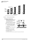
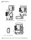
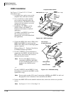
³ When packaging and storing the system, remove PCBs from the system cabinet (the power
supply may remain installed in the cabinet for storage and shipment). PCBs should be
packaged in their original antistatic bags for protection against electrostatic discharge. Be sure
to package equipment in its original shipping containers.
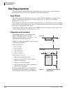
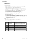
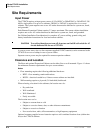
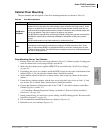
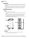
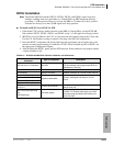
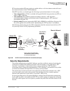
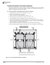
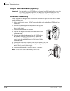
Site Requirements
This section defines the installation site requirements necessary to ensure a proper operating
environment for the CTX100. Also included are grounding requirements.
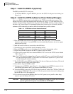
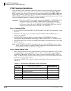
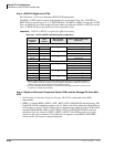
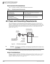
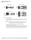
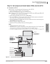
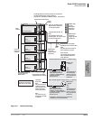
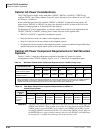
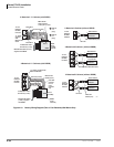
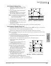
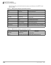
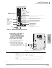
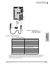
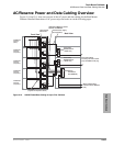
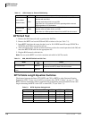
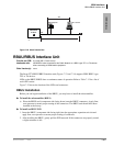
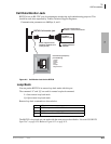
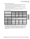
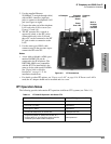
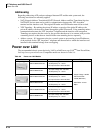
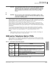
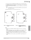
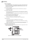
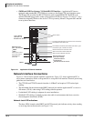
Input Power
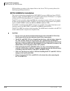
The Base Cabinet or the Base and Expansion Cabinet together require an input power source of
120VAC, 60 Hz, 15 amps. Each cabinet plugs into an AC power outlet. Each cabinet requires 1.8
amps AC from the power source or 3.6 amps AC combined. The power supply cord for each
cabinet is 4.5 ft. long with a standard three-prong 120VAC plug.