


ISDN Interfaces
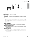
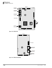
RBSU/RBSS Interface Units
7-24 Strata CTX I&M 06/04
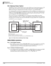
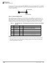
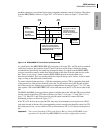
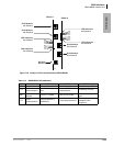
Most NT1 devices have TR option switches; if the NT1 does not have TRs, two 100-ohm TRs
must be wired into the NT1 modular jack - one 100-ohm resistor across each pair (Tx and Rx).
Refer to the NT1 manufacturers documentation for the maximum loop length between the NT1
and the network jack. The maximum loop length between the NT1 and the RBSU circuit is 1650
feet.
Figure 7-17 RBSU to NT1 Point-to-point Connection
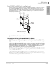
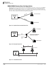
Connecting RBSU/RBSS Station Devices (NT-Mode)
S-type TAs and TE-1s can be connected to the station side of TBSU, RBSU, and RBSS circuits.
TA and TE devices must be powered by local AC power using AC adapter supplied with the TA or
TE device. The RBSU/RBSS circuits must be configured in the NT mode when connected to TA
and TE devices (refer to option switches in Table 7-8 on page 7-17 and Table 7-11 on page 7-22).
The TA enables you to connect non-ISDN voice and data devices to ISDN BRI circuits. The TA
matches the protocol of existing interfaces (R-reference point) to the ISDN S/T protocol (see
Figure 7-1 on page 7-2). TA devices include asynchronous circuit-switched adapters that convert
RS-232 sync data (like data from a PC COM port) to B-channel 64 kbps sync.
TAs also enable you to connect standard telephones and non-ISDN fax machines to receive and
make calls over ISDN circuits. TEs include any user device (telephone, fax, PC video conference
board) that is designed to plug directly into the ISDN (S/T) interface without the use of a TA.
There are two types of ISDN TA and TE-1 devices: the U-type and the S/T type. Most
manufacturers of ISDN station devices make both types. On the RBSU/RBSS station side,
BRI-NT circuits only function with S/T type TA and TE-1 devices. You cannot connect U-type
TE-1 or TA devices to the RBSU/RBSS BRI-NT circuits.
Also, connecting an NT1 to the RBSU/RBSS BRI-NT circuit to convert from S/T to U interface is
not supported to enable the use of U-type TE-1 or TA device on the station side of the RBSU/
RBSS. U-type TE-1 and TA device interface is provided in the Strata CTX by the RBUU/RBUS
BRI circuit only.
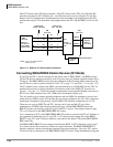
The RBSU/RBSS BRI-NT circuit supports the National ISDN 2 (NI2) S-Interface “passive bus.”
It is called a passive bus, because it contains no logical functions. The RBSU/RBSS BRI-NT
interface supports a point-to-multipoint connection on two twisted pairs. Up to two TE-1 and/or
TA devices can be connected to one RBSU/RBSS, BRI-NT circuit. Using standardized wiring and
RBSU
TE-Circuit
Switch in
100-ohm TR
using RBSU
option switch.
RJ45 Pinout
(RBSU - BRI jack)
5433
Network
BRI-line
RJ11 Jack
NT-1
Switch
in 100-ohm
TR.
T and U are ISDN standard
reference points.
Note:
BRI
(four-wire)
T
BRI
(two-wire)
U
Demarcation Point
3
6
4
5
3
6
4
5
RX
RX
TX
RXTX
TX
RX TX
RX/TX
RX/TX4
5
RJ45 Pinout
(NT1 - S/T jack)
Local AC
Power